

How to Lay Out Foundation Rebar Before the Pour
For a foundation rebar layout, start with the approved plans. Mark each bar’s size, direction, and spacing; lay out the footing bars or slab grid; then tie the bars and support them at the specified height. Check corners, splices, and wall dowels before the pour. Where concrete is cast directly against earth, keep at least 3 inches of clear cover between the steel and the soil. Use the plans for all other cover and placement requirements.
That last check matters: concrete handles compression well, but reinforcement helps it resist bending and tension. A neat grid cannot do its job if the bars sink or shift as concrete is placed.
I’m Jordan Harris, a Tennessee-licensed professional engineer who spent five years working on large concrete and steel projects. Today, I bring that experience to rebar support design at Hercules Rebar Chairs, with a focus on keeping each foundation rebar layout in place through the pour.
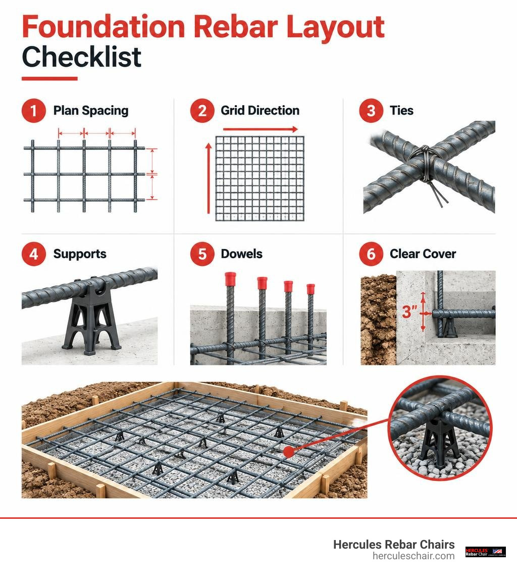
Simple foundation rebar layout glossary:
Structural Fundamentals and Code Standards for Reinforcing Steel
Concrete is an absolute champion when it comes to supporting downward compressive weight. However, plain concrete possesses only about 10% of its compressive strength when subjected to pulling, twisting, or bending forces (tensile strength). Without steel reinforcing bars embedded inside, a concrete foundation behaves like an oversized, brittle rock. The moment uneven soil settlement, frost heaving, or lateral backfill pressure pulls on the bottom or sides of a footing, unreinforced concrete snaps.
When we integrate deformed steel bars into the tension zones of concrete elements, we create a composite structural unit. The deformations on the steel ridges mechanically lock into the concrete paste, transferring tensile loads directly into the steel. But placing rebar is not just about tossing metal into a trench; mastering rebar placement for foundation longevity requires understanding internal stress dynamics and corrosion mechanics.
If steel is placed too close to the edge or bottom of the concrete, moisture and oxygen penetrate the porous concrete matrix. This triggers oxidation. As steel corrodes, it expands to 2 to 3 times its original volume—a destructive process known as oxide jacking. The internal expansion pressure easily exceeds concrete’s tensile limit, causing the foundation to crack, spall, and disintegrate from the inside out. Without proper reinforcement positioning, concrete can lose up to 35% of its structural load-bearing capacity.
| Rebar Size (US Standard) | Nominal Diameter | Cross-Sectional Area | Standard Yield Strength (Grade 60) | Typical Foundation Application |
|---|---|---|---|---|
| #3 | 3/8 inch (0.375″) | 0.11 sq. in. | 60,000 psi | Slab temperature and shrinkage mesh, light stirrups |
| #4 | 1/2 inch (0.500″) | 0.20 sq. in. | 60,000 psi | Residential continuous footings, stem wall verticals, slab mats |
| #5 | 5/8 inch (0.625″) | 0.31 sq. in. | 60,000 psi | Heavy residential footings, high backfill basement walls, grade beams |
| #6 | 3/4 inch (0.750″) | 0.44 sq. in. | 60,000 psi | Commercial spread footings, deep column pads, severe load zones |
Sizing, Spacing, and Concrete Cover Specifications
Most modern residential and light commercial structural plans call for Grade 60 deformed carbon steel bars compliant with ASTM A615, offering a minimum yield strength of 60,000 psi. In standard residential continuous footings, #4 bars serve as the baseline industry standard, while #5 bars are routinely specified for larger multi-story structures, basement retaining walls, or expansive clay soils.
Spacing must strictly balance load distribution against aggregate flow. Standard residential on-center spacing is 12 inches, with building codes establishing an absolute maximum allowable spacing of 18 inches. Furthermore, the clear gap between parallel bars must be at least 1.5 times the bar diameter (and at least 1.33 times the maximum aggregate size) to allow the coarse gravel in the mix to pass through without forming honeycombs or voids.
Clear concrete cover protects the steel against moisture intrusion and ensures adequate bond strength per ACI 318 design guidelines:
- Concrete cast against and permanently in contact with earth: 3 inches minimum clear cover.
- Concrete exposed to weather or earth after form removal: 1.5 inches for #5 bars and smaller (2 inches for #6 bars and larger).
- Interior concrete not exposed to weather: 0.75 inches for slabs and walls.
Seismic Design Categories and Lateral Load Requirements
In regions classified under Seismic Design Categories D0, D1, and D2, ground acceleration introduces severe dynamic shear forces and uplift moments. Foundations must resist not only the static downward weight of the home, but also cyclical lateral sliding forces through a combination of bottom-surface friction and passive soil pressure along the vertical face.
Under International Residential Code (IRC) Section R403, seismic foundation reinforcement requirements mandate continuous vertical and horizontal steel ties. In stem walls, vertical #4 bars must be installed at a maximum interval of 48 inches on-center, terminating in standard hooks near the footing bottom and extending at least 14 inches up into the stem wall. Horizontally, at least one #4 bar must run within 12 inches of the top of the stem wall and another must sit 3 to 4 inches above the bottom of the footing.
The structural value of these details was proven during the 1994 Northridge earthquake (magnitude 6.7), where residential structures built with properly reinforced, code-compliant foundations experienced approximately 60% less structural damage than unreinforced concrete counterparts under identical soil conditions.
Step-by-Step Foundation Rebar Layout Execution for Slabs and Footings
A successful layout bridges the gap between engineering drawings and real-world jobsite conditions. Preparing the ground correctly ensures that steel remains level and stays within code tolerances throughout the concrete pour.
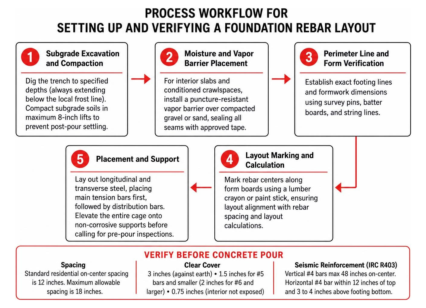
- Subgrade Excavation and Compaction: Dig the trench to specified depths (always extending below the local frost line). Compact subgrade soils in maximum 8-inch lifts to prevent post-pour settling.
- Moisture and Vapor Barrier Placement: For interior slabs and conditioned crawlspaces, install a puncture-resistant vapor barrier over compacted gravel or sand, sealing all seams with approved tape.
- Perimeter Line and Form Verification: Establish exact footing lines and formwork dimensions using survey pins, batter boards, and string lines.
- Layout Marking and Calculation: Mark rebar centers along form boards using a lumber crayon or paint stick, ensuring layout alignment with rebar spacing and layout calculations.
- Placement and Support: Lay out longitudinal and transverse steel, placing main tension bars first, followed by distribution bars. Elevate the entire cage onto non-corrosive supports before calling for pre-pour inspections.
Executing a proper rebar layout for concrete footings prevents field adjustments that delay concrete trucks.
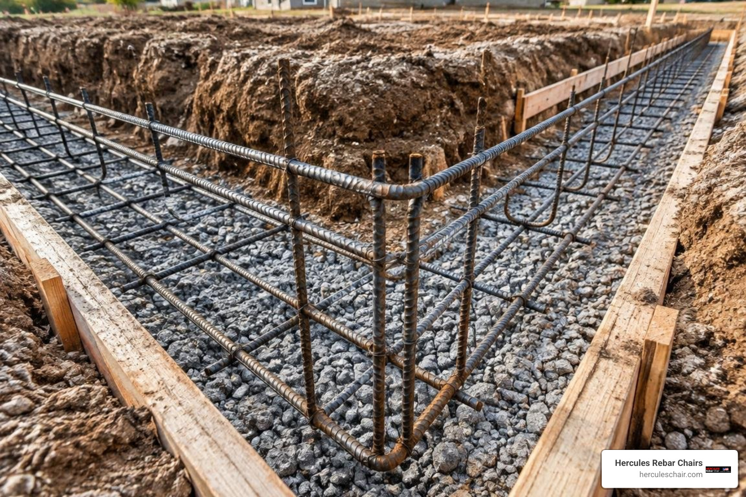
Step-by-Step Foundation Rebar Layout for Continuous Footings and Stem Walls
Continuous strip footings distribute load-bearing wall weights across the subgrade. When setting up continuous footings:
- Trench Clearing: Remove all loose soil, standing water, mud, roots, and organic debris from the trench bottom.
- Short-Span Placement First: If placing a bottom mat in wide spread footings, place the transverse bars (spanning the short direction) first, as this is where maximum bending tension concentrates.
- Longitudinal Distribution Bars: For standard continuous footings, place two parallel #4 or #5 bars running lengthwise along the trench. Maintain equal edge clearance on both sides.
- Elevation Off Dirt: Elevate bars so they sit in the tension zone (the bottom third of the footing thickness), while strictly maintaining at least 3 inches of clear space off the dirt.
- Stem Wall Rebar Alignment: When stem walls sit on the footing, align horizontal bars in the upper third of the wall formwork and ensure all vertical dowels are centered.
To avoid running short of material during installation, review our guide on calculating rebar requirements for foundations to account for bar laps and standard 10% jobsite waste factors. By using proper footing rebar layout techniques, your footing forms a rigid structural spine capable of spanning soft spots in the subgrade.
Monolithic Slab Foundation Rebar Layout and Spread Footing Grids
Monolithic (turned-down) slabs combine the structural footing and interior floor slab into a single continuous concrete pour. Per IRC R403.1.3.2, the thickened perimeter turned-down edge requires either one #4 bar located at both the top and bottom of the footing trench, or one #5 bar (or two #4 bars) centered within the middle third of the footing depth.
For the interior floor slab, lay out a two-way grid of #3 or #4 bars spaced 12 to 18 inches on center in both directions. In isolated rectangular spread footings, flexural reinforcement must be laid out according to footing reinforcement details and layouts and Division of the State Architect guidelines, which require a banded concentration of rebar across the center zone in the short direction to resist high concentrated column punching shear.
Essential Detailing: Splices, Corners, Vertical Dowels, and Tying
The structural strength of a rebar cage depends on its connections. Unsecured bars, short lap splices, or unreinforced corners create localized failure planes that compromise the entire foundation.
When tying steel intersections, use 16-gauge black annealed tie wire. Common tying methods include:
- Snap Tie (Single Tie): Quick and effective for flat, horizontal slab grids with minimal movement risk.
- Wrap and Snap Tie: Wraps completely around the bar before snapping, adding extra grip for vertical dowels.
- Saddle Tie (U-Tie): Loops under the bottom bar and crosses over the top bar, providing strong resistance against downward and sideways slipping.
- Figure-Eight Tie: Combines high rigidity and holding power, ideal for securing heavy corner bars and column cages.
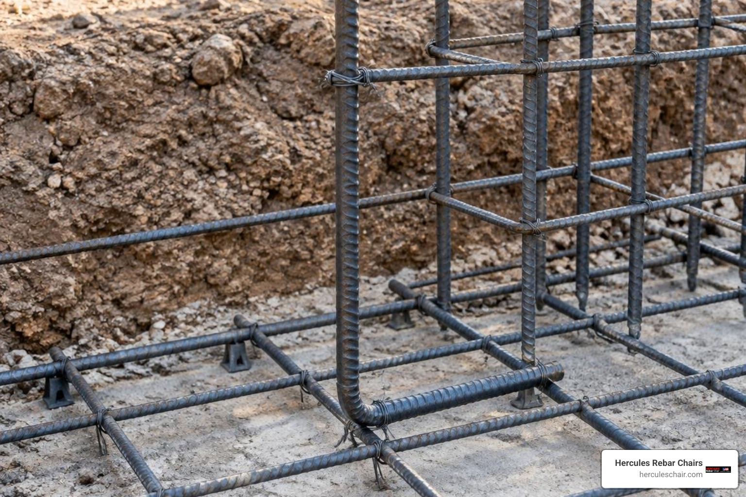
Lap Splices, Corner Bars, and Intersection Details
Because rebar comes in standard 20-foot or 40-foot lengths, long foundation runs require lap splices to maintain tensile continuity. A reliable rule of thumb for lap splice length is 40 times the nominal bar diameter (40d):
- #4 Bar (1/2″ diameter): 40 × 0.5 inches = 20-inch minimum lap.
- #5 Bar (5/8″ diameter): 40 × 0.625 inches = 25-inch minimum lap.
- #6 Bar (3/4″ diameter): 40 × 0.75 inches = 30-inch minimum lap.
Always stagger lap splices by at least 24 inches so that adjacent parallel bars do not lap at the exact same point along the footing.
At foundation corners, simply butting straight horizontal bars together creates a weak hinge. Corners require continuous 90-degree bent corner bars (L-bars) matching the diameter of the horizontal steel. These corner bars must extend around the bend by at least the required lap length (e.g., 20 inches for #4 bars) in both directions. Review these foundation design tips to prevent structural failure to ensure corner intersections resist lateral soil loads without pulling apart.
Vertical Dowel Anchoring vs. Wet-Setting Pitfalls
Vertical connection dowels lock the footing to the stem wall, masonry block wall, or column above. These L-shaped bars hook directly under the bottom horizontal footing steel and extend upward a minimum of 14 to 24 inches into the future wall pour, spaced at a maximum of 4 feet on center.
One of the most destructive jobsite shortcuts is “wet-stabbing” or pushing vertical dowels into freshly poured footing concrete. Wet-setting is strictly prohibited by code for several critical reasons:
- Aggregate Displacement: Pushing a bar into wet concrete shoves coarse aggregate away, leaving the steel surrounded solely by weak cement paste (“cream”) and water.
- Internal Air Voids: As the bar is inserted and jiggled, it traps air pockets along its length, drastically reducing mechanical bond strength and pullout resistance.
- Loss of Clear Cover: Wet-stabbed bars drift unpredictably, often sinking all the way through to the wet mud beneath the footing, guaranteeing rapid corrosion and oxide jacking.
All vertical dowels must be securely tied to the horizontal footing cage before placing concrete.
Supporting, Inspecting, and Protecting Reinforcement
A rebar grid laid on the ground offers zero structural benefit. Shifting rebar by just half an inch in a 6-inch slab reduces its load-carrying capacity by 20%. To perform as designed, the entire steel assembly must be permanently elevated and supported throughout the pour.
| Application Type | Recommended Rebar Support | Support Spacing Interval | Clear Cover Maintained |
|---|---|---|---|
| Continuous Earth-Cast Footing | Stable 2-bar footer stands / chairs | Every 3 to 4 feet along trench | 3.0 inches clear off subgrade |
| Monolithic Slab-on-Grade | Heavy-duty non-directional slab chairs | Every 3 feet on-center grid | 1.5 to 2.0 inches clear from bottom |
| Basement Walls / Stem Forms | Side-form spacer wheels / clip chairs | Every 3 to 4 feet vertically & horizontally | 1.5 inches clear to formwork |
| Two-Way Column Spread Footing | High-capacity structural rebar stands | Every 2.5 to 3 feet in both directions | 3.0 inches clear off ground |
Elevation Supports and Proper Chair Placement
To ensure stable support, place rebar chairs every 3 to 4 feet along the length of each bar. Using improper supports like broken bricks, wood scraps, or flat rocks is a major code violation; porous masonry absorbs ground moisture, while wood rots, creating direct channels for water to reach the steel.
We manufacture Hercules Rebar Chairs (by T.J. Harris Co.) right here in the USA, providing contractors with rugged, non-corrosive, high-strength polypropylene supports that will not crack under heavy foot traffic. As America’s #1 rebar chair with over 14 million units sold, our distinct red chairs snap securely onto #3, #4, and #5 bars, maintaining exact clear cover without shifting when concrete is pumped and vibrated.
For complete layout details, see our guide on spacing and supporting footing rebar and follow our footer stand placement guidelines to prevent point-load displacement.
Pre-Pour Inspection Criteria and Corrosion Protection
Before calling your local building official for the mandatory foundation inspection, verify every item against the municipal residential footing inspection checklist:
- Setbacks and Trench Dimensions: Verify trench width and depth match approved plans and exceed local frost lines.
- Trench Cleanliness: Ensure trenches are clean and free of water, mud, roots, and loose spoils.
- Clearance Verification: Confirm at least 3 inches of clear cover off raw soil and 1.5 inches to form boards.
- Lap Splices and Ties: Check that all splices meet the 40d minimum length and are firmly wired.
- UFER Electrical Ground: Verify that the concrete-encased electrode (UFER ground) utilizes a #4 rebar with at least a 12-inch lap attached with 3 tight wire ties to the main horizontal footing steel, stubbing up 12 inches above the plate line.
- Visual Inspection Advantage: Our red Hercules Rebar Chairs make it easy for building inspectors to verify proper cover and spacing from the trench edge, speeding up pre-pour approvals.
For projects in coastal environments, high-water-table areas, or chemically corrosive soils, consider corrosion-resistant reinforcement options such as epoxy-coated, galvanized, or stainless steel rebar. Light surface rust on standard black rebar is completely normal and actually improves mechanical bonding with concrete paste. However, heavy, flaky rust scale or deep pitting indicates loss of cross-sectional area; damaged bars must be cleaned with a wire brush or replaced.
Frequently Asked Questions About Foundation Reinforcement
What is the standard rebar size and spacing for residential footings?
For most one- and two-story residential homes in the United States, #4 rebar (1/2-inch diameter) is the standard for continuous footings and stem walls. Standard horizontal rebar spacing is 12 inches on center, with building codes allowing a maximum spacing of 18 inches. In areas with expansive clay soils or heavy multi-story loads, structural plans frequently upgrade reinforcement to #5 bars (5/8-inch diameter).
Why is wet-setting vertical rebar into wet concrete prohibited?
Wet-setting (pushing dowels into wet concrete after pouring) shoves coarse aggregate away from the steel, leaving the bar encased only in weak cement paste. This creates internal air voids that compromise pullout strength and bond capacity. Additionally, wet-set bars often sink too deep, contacting wet earth and causing rapid steel corrosion and concrete spalling.
How much overlap is required for rebar lap splices?
Building codes require a minimum tension lap splice length equal to 40 times the bar diameter (40d). For standard #4 rebar, this equates to a 20-inch minimum overlap; for #5 rebar, the minimum lap is 25 inches; and for #6 rebar, it is 30 inches. Splices should always be staggered so adjacent parallel bars do not lap at the same location.
Conclusion
A durable foundation requires precise planning, code-compliant rebar sizing, accurate lap splices, and dependable elevation support. By taking the time to lay out your rebar grid methodically, tie every intersection securely, and maintain your 3-inch clear cover off the soil, you ensure your concrete structure will remain stable for decades to come.
Do not leave your foundation’s structural integrity to chance. Plan your jobsite reinforcement supports using the Hercules Rebar Chair estimator to get the right support layout and chair count for your next pour.