

How to Calculate Rebar for a Residential Slab
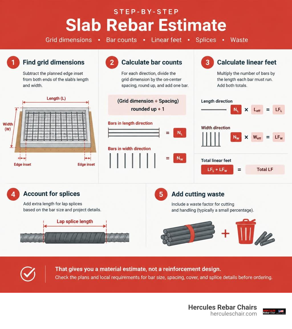
For a rectangular slab, calculate the rebar in each direction, then add the lengths. Subtract the planned edge inset from both ends of the slab’s length and width to get the grid dimensions. For each direction, divide the grid dimension by the on-center spacing, round up, and add one bar. Then multiply the number of bars by the length each bar must run. Add both totals to get linear feet of rebar before allowing for lap splices and cutting waste.
That gives you a material estimate, not a reinforcement design. Check the plans and local requirements for bar size, spacing, cover, and splice details before ordering.
I’m Jordan Harris, a Tennessee-licensed professional engineer with a master’s degree in structural engineering and five years of experience on large concrete and steel projects. At T.J. Harris Company, I use the rebar calculation formula to help turn slab layouts into practical material estimates.
Rebar calculation formula helpful reading:
The Core Rebar Calculation Formula for Concrete Slabs
Concrete is exceptionally strong under compression, but it is naturally weak in tension. When tensile stresses or temperature shifts act on a slab, steel reinforcement carries the load to keep cracks tight and maintain structural integrity. Getting your material count right ensures you avoid costly mid-pour delays while eliminating unnecessary scrap steel.

To calculate rebar for your concrete slab accurately, you must establish proper bar measurements based on your slab geometry, clearance rules, and spacing requirements.
Calculating Grid Dimensions and Bar Counts
You do not run rebar all the way to the outer edge of the formwork. Doing so exposes the steel to moisture and soil, leading to corrosion and spalling. Standard building practices demand an edge inset (concrete cover) on all sides.
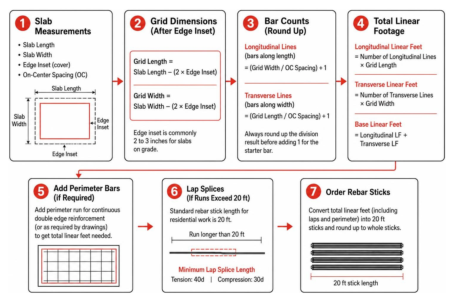
First, determine the actual grid dimensions:
- Grid Length = Slab Length – (2 × Edge Inset)
- Grid Width = Slab Width – (2 × Edge Inset)
For residential slabs on grade, the edge inset is commonly 2 to 3 inches.
Once you have your grid dimensions, calculate the number of bar runs needed in each direction based on the on-center (OC) spacing. Typical residential applications such as driveways, sidewalks, and garage slabs specify 12-inch, 18-inch, or 24-inch on-center grid patterns, which you can balance against your specific patio reinforcement ratios.
To find the number of bars running along the length (transverse bars spaced across the width):
- Number of Longitudinal Lines = (Grid Width / On-Center Spacing) + 1
To find the number of bars running along the width (longitudinal bars spaced across the length):
- Number of Transverse Lines = (Grid Length / On-Center Spacing) + 1
Always round up the division result to the nearest whole number before adding 1 for the starter bar.
Total Linear Footage Equation for Rectangular Pours
With the bar run counts established, compute the total linear footage before splices. Each longitudinal line runs the full grid length, and each transverse line runs the full grid width:
- Longitudinal Linear Feet = Number of Longitudinal Lines × Grid Length
- Transverse Linear Feet = Number of Transverse Lines × Grid Width
- Base Linear Feet = Longitudinal Linear Feet + Transverse Linear Feet
If your engineering drawings require perimeter detailing, such as continuous double edge reinforcement to handle vehicle loads on driveway aprons, add the perimeter run to this total. Factoring in perimeter bars gives you the baseline footage necessary for comprehensive concrete slab reinforcement.
Using the Rebar Calculation Formula for Lap Splices and Stick Quantities
Standard reinforcement steel in the United States is sold in pre-cut stick lengths, typically 20-foot sticks for residential work (with 40-foot and 60-foot lengths common in heavy commercial jobs). When a slab run exceeds 20 feet, two or more bars must overlap to transfer tensile stresses continuously.
According to ACI 318 structural concrete reinforcement fundamentals, the minimum lap splice length for tension splices is generally 40 times the nominal bar diameter (40d), while compression splices require at least 30 times the bar diameter (30d):
- For #3 rebar (3/8-inch diameter): 40 × 0.375 in = 15 inches of overlap
- For #4 rebar (1/2-inch diameter): 40 × 0.500 in = 20 inches of overlap
- For #5 rebar (5/8-inch diameter): 40 × 0.625 in = 25 inches of overlap
For every continuous line longer than a standard 20-foot stick, calculate the number of splices:
- Splices Per Line = (Grid Run Length / 20 ft), rounded down
Multiply the number of splices by the required lap length (converted to feet), and add this total splice length to your base linear feet:
- Total Linear Feet = Base Linear Feet + (Total Number of Splices × Lap Length in Feet)
To determine how many 20-foot sticks you must purchase:
- Number of Sticks = Total Linear Feet / 20 ft (rounded up to the nearest whole stick)
Converting Linear Footage to Weight and Total Project Cost
Steel mills and distributors often price and transport rebar by total weight (hundredweight or tons) rather than linear feet. Converting your linear footage to weight helps you budget material expenses accurately and verify delivery vehicle capacities.
| Rebar Size (US Imperial) | Nominal Diameter (inches) | Nominal Diameter (mm) | Weight per Foot (lbs/ft) | Weight per Meter (kg/m) |
|---|---|---|---|---|
| #3 | 0.375 in (3/8″) | 9.525 mm | 0.376 lbs/ft | 0.560 kg/m |
| #4 | 0.500 in (1/2″) | 12.700 mm | 0.668 lbs/ft | 0.994 kg/m |
| #5 | 0.625 in (5/8″) | 15.875 mm | 1.043 lbs/ft | 1.552 kg/m |
| #6 | 0.750 in (3/4″) | 19.050 mm | 1.502 lbs/ft | 2.235 kg/m |
| #7 | 0.875 in (7/8″) | 22.225 mm | 2.044 lbs/ft | 3.042 kg/m |
| #8 | 1.000 in (1″) | 25.400 mm | 2.670 lbs/ft | 3.973 kg/m |
Selecting the correct gauge depends on slab thickness and anticipated loads, following standard rebar sizes and grades.
Weight Formulas for Imperial and Metric Projects
In the US Imperial system, rebar size numbers represent eighths of an inch. A #4 bar is 4/8-inch (1/2-inch), and a #8 bar is 8/8-inch (1-inch).
To calculate the total weight in pounds:
- Total Weight (lbs) = Total Linear Feet × Unit Weight per Foot (lbs/ft)
For projects using metric measurements, calculating weight per meter utilizes the standard density of steel (7,850 kg/m³). You can calculate the unit weight using the diameter squared formula:
- Weight per Meter (kg/m) = (Diameter in mm × Diameter in mm) / 162
To find metric total weight:
- Total Weight (kg) = Total Length (meters) × [(Diameter in mm)² / 162]
You can cross-reference these calculations using an online rebar weight calculator or follow our guide on calculating rebar weight in kilograms to double-check your numbers.
Material Waste Allowance and Total Cost Estimation
On real construction sites, bars must be cut to fit inside formwork, leaving unusable short drops. Always add a 10% material waste allowance to your total linear footage before placing an order.
- Ordered Linear Feet = Total Linear Feet × 1.10
- Ordered Sticks = Ordered Linear Feet / Single Stick Length (rounded up)
To estimate total material cost:
- Total Cost = Ordered Sticks × Cost per Stick (or Ordered Weight in Tons × Price per Ton)
Factoring in weight is equally crucial for logistics. Standard half-ton and three-quarter-ton pickup trucks have payload capacities between 1,000 and 1,500 pounds. A driveway requiring 2,150 linear feet of #5 rebar weighs approximately 2,242 pounds, which exceeds standard pickup limits and requires a heavy-duty trailer or supplier freight delivery.
Advanced Formulas: Irregular Slab Shapes and Concrete Displacement
Not every concrete pour is a clean rectangle. Freeform patios, pool decks, and curved driveways require adjusted mathematical estimation methods. You can consult engineering guidelines like the BAR Reinforcement Desktop Toolkit for complex shapes, or use simplified geometric area formulas.
Irregular Slab Estimation: The Modified Rebar Calculation Formula
For irregular or curved slabs where individual bar runs vary across the layout, you can determine the total single-mat rebar length using the area-perimeter method:
- Total Rebar Length = [4 × Spacing × (Adjusted Area / (2 × Spacing × Spacing))] + (Adjusted Perimeter / 2)
Where:
- Spacing is the on-center bar spacing in feet.
- Adjusted Area is the surface area of the slab in square feet minus the edge inset margin.
- Adjusted Perimeter is the slab perimeter in linear feet adjusted for the inset.
To approximate the inset adjustment for an irregular shape:
- Treat the shape as an equivalent circle with radius R = Square Root of (Area / 3.14159).
- Subtract your edge inset (in feet) from R to find the adjusted radius (r_adj).
- Compute Adjusted Area = 3.14159 × radj × radj.
- Compute Adjusted Perimeter = 2 × 3.14159 × r_adj.
Applying this modified formula gives an accurate, non-conservative linear footage estimate for irregular pours.
Concrete Volume Displaced by Steel Reinforcement
Rebar occupies physical space inside the forms. In heavily reinforced slabs or footings, steel displacement can slightly reduce the net volume of ready-mix concrete required.
To calculate the volume of concrete displaced by steel:
- Bar Cross-Sectional Area (sq in) = 3.14159 × (Bar Diameter / 2)²
- Bar Volume (cu in) = Bar Cross-Sectional Area × Total Linear Feet × 12
- Displaced Volume (cu yd) = Bar Volume / 46,656
For a standard residential patio using 360 linear feet of #4 rebar:
- Bar Cross-Sectional Area = 3.14159 × (0.25 in)² = 0.1963 sq in
- Bar Volume = 0.1963 sq in × 360 ft × 12 in/ft = 848.2 cu in
- Displaced Concrete = 848.2 cu in / 46,656 cu in/cu yd = 0.018 cu yd
Because residential displacement is typically less than 0.05 cubic yards, standard concrete batching orders (which round up to the nearest quarter or half yard to accommodate subgrade unevenness) do not require downward adjustments. However, on large commercial civil jobs with dense multi-mat steel, subtracting displaced volume prevents significant concrete over-ordering.
Estimating Hardware: Support Chairs and Tie Wire Quantities
A perfectly calculated rebar grid fails if it sits flat on the dirt or gravel subbase. Pulling rebar up with hooks during the pour is unreliable and violates ACI building standards. ACI 318 requires maintaining at least 3 inches of clear concrete cover when concrete is cast against earth, and 1.5 inches of cover from finished surfaces. Reinforcement must be elevated on sturdy chairs before the pour begins, ensuring proper foundation reinforcement.

Calculating Rebar Chair Quantities and Placement Patterns
Rebar chairs must support the weight of the steel grid and the workers walking across it without buckling or punching into the subbase. To prevent grid sagging, chairs should be spaced every 2 to 3 feet in both directions along the grid lines, as well as near perimeter edges.
To calculate the total number of rebar chairs needed:
- Method 1 (Area Estimate): Provide 1 chair for every 6 to 8 square feet of slab area.
- Number of Chairs = Slab Area (sq ft) / 7
- Method 2 (Grid Intersection Count): Count the total grid intersections and place chairs at every second or third intersection.
- Number of Chairs = (Longitudinal Lines × Transverse Lines) / 2.5
We at Hercules Rebar Chairs (T.J. Harris Co.) have manufactured over 14 million of our signature red rebar chairs right here across the USA. Designed to ensure strict code compliance while saving contractors installation time, our durable chairs provide rock-solid support so your steel stays exactly where engineers intended.
Tie Wire Weight and Fastener Formulas
Tie wire holds intersecting bars in place so the grid remains rigid during the pour. Standard construction practice uses 16-gauge annealed steel tie wire.
You do not need to tie every single intersection. In residential flatwork, tying every other intersection in a checkerboard pattern across the field—and tying every intersection along the outer perimeter—provides structural rigidity.
To estimate tie wire requirements:
- Total Grid Intersections = Longitudinal Lines × Transverse Lines
- Number of Ties Required = Total Grid Intersections × 0.50 (for checkerboard tying) + Perimeter Intersections
- Wire Weight Rule: Plan for approximately 1 pound of 16-gauge tie wire per 100 linear feet of rebar.
- Tie Wire (lbs) = Total Linear Feet of Rebar / 100
A single 3.5-pound coil of 16-gauge tie wire yields roughly 250 individual ties, making it easy to convert your calculated tie count into full wire rolls.
Frequently Asked Questions About Slab Rebar Calculations
What is the standard rebar lap splice length for residential slabs?
Per ACI 318 standards, the rule of thumb for tension lap splices is 40 times the bar diameter (40d). For #3 rebar, that is 15 inches; for #4 rebar, it is 20 inches; and for #5 rebar, it is 25 inches. For compression splices, 30 times the bar diameter is standard (15 inches for #4 rebar). Always verify splice details against your structural drawings.
How much rebar is needed for a 20×20 garage slab?
For a 20 ft × 20 ft slab with a 3-inch edge inset, the rebar grid measures 19.5 ft × 19.5 ft. With #4 rebar spaced at 12 inches on center:
- Longitudinal lines: (19.5 / 1) + 1 = 21 lines of 19.5 ft = 409.5 linear feet
- Transverse lines: (19.5 / 1) + 1 = 21 lines of 19.5 ft = 409.5 linear feet
- Base footage: 819 linear feet
- Adding a 10% waste allowance: 819 × 1.10 = 901 linear feet
- Total sticks: 901 / 20 = 46 sticks of 20-foot rebar (weighing approximately 602 lbs).
How does GFRP rebar calculation differ from standard steel?
Glass Fiber Reinforced Polymer (GFRP) rebar follows the same linear footage and grid layout geometry as steel. However, GFRP is roughly 75% lighter than steel. On a 20 ft × 20 ft grid with 12-inch spacing requiring 42 bars, a worker can carry approximately 17 GFRP bars per trip compared to only 5 steel bars. This cuts carry trips by more than half and reduces installation time from roughly 75 minutes down to 25 minutes, saving approximately $115 in combined labor and handling.
Conclusion
Mastering the rebar calculation formula prevents costly estimation errors, eliminates material waste, and guarantees that your concrete slabs withstand heavy loads and ground movement over decades of service. By accurately establishing edge insets, determining run counts, accounting for lap splices, and adding a sensible 10% waste factor, you can order materials with confidence.
Once your rebar arrives on site, keeping it elevated is critical to structural performance. We at Hercules Rebar Chairs (T.J. Harris Co.) are proud to be America’s #1 choice for rebar supports, with over 14 million of our signature red chairs sold across the United States. To find the exact number of chairs and supports your project requires, try our free Hercules Rebar Chair Estimator today.