

Understanding the Imperial Sizing System for Rebar Sizes in Inches
Standard rebar sizes in inches follow a simple rule for #3 through #8 bars: divide the bar number by eight. For example, a #4 bar is 4/8 in. = 0.500 inches, and a #8 bar is 8/8 in. = 1.000 inch. This imperial sizing framework is governed by ASTM A615 standards, which assigns numbers to reinforcing steel bars according to a standardized system. As explained in the essential guide to rebar sizes and grades, this numbering system simplifies how structural engineers, estimators, and rodmen communicate on drawings and material schedules.
Rather than writing out complex fractional decimals for every bend and splice, standard structural callouts use a straightforward bar number (such as #4 or #5).
This notation governs everything from lap splice lengths to the concrete clear cover required under standard building codes.
Calculating Standard Rebar Sizes in Inches from Bar Numbers
For standard small-to-medium bars (#3 through #8), determining the nominal diameter in inches is straightforward: divide the bar callout number by eight.
- #3 Bar: $3/8\text{ in.} = 0.375\text{ inches}$ ($9.5\text{ mm}$)
- #4 Bar: $4/8\text{ in.} = 1/2\text{ in.} = 0.500\text{ inches}$ ($12.7\text{ mm}$)
- #5 Bar: $5/8\text{ in.} = 0.625\text{ inches}$ ($15.9\text{ mm}$)
- #6 Bar: $6/8\text{ in.} = 3/4\text{ in.} = 0.750\text{ inches}$ ($19.1\text{ mm}$)
- #7 Bar: $7/8\text{ in.} = 0.875\text{ inches}$ ($22.2\text{ mm}$)
- #8 Bar: $8/8\text{ in.} = 1\text{ in.} = 1.000\text{ inch}$ ($25.4\text{ mm}$)
The #8 bar is a clean 1.000-inch baseline for engineers and concrete crews when checking material sizes on site.
Why Large Bars Deviate from the Eighth-Inch Rule
Dividing by eight no longer applies when moving past a #8 bar. A #9 bar is not $9/8$ ($1.125$) inches, and a #10 bar is not $10/8$ ($1.250$) inches.
Historically, large reinforcement bars were manufactured with square profiles (such as 1-inch square, 1-1/8-inch square, and 1-1/4-inch square bars). When the steel industry standardized round deformed bars under modern ASTM specifications, these larger sizes were engineered to match the cross-sectional area of the old square bars rather than an arbitrary diameter fraction:
- A #9 bar has a cross-sectional area of $1.00\text{ sq. in.}$, matching an old $1\text{ in.} \times 1\text{ in.}$ square bar. Its nominal round diameter is $1.128\text{ inches}$.
- A #10 bar has an area of $1.27\text{ sq. in.}$, matching an old $1\text{-}1/8\text{ in.}$ square bar. Its nominal round diameter is $1.270\text{ inches}$.
- A #11 bar has an area of $1.56\text{ sq. in.}$, matching an old $1\text{-}1/4\text{ in.}$ square bar. Its nominal round diameter is $1.410\text{ inches}$.
- A #14 bar has an area of $2.25\text{ sq. in.}$, matching an old $1\text{-}1/2\text{ in.}$ square bar. Its nominal round diameter is $1.693\text{ inches}$.
- A #18 bar has an area of $4.00\text{ sq. in.}$, matching an old $2\text{ in.} \times 2\text{ in.}$ square bar. Its nominal round diameter is $2.257\text{ inches}$.
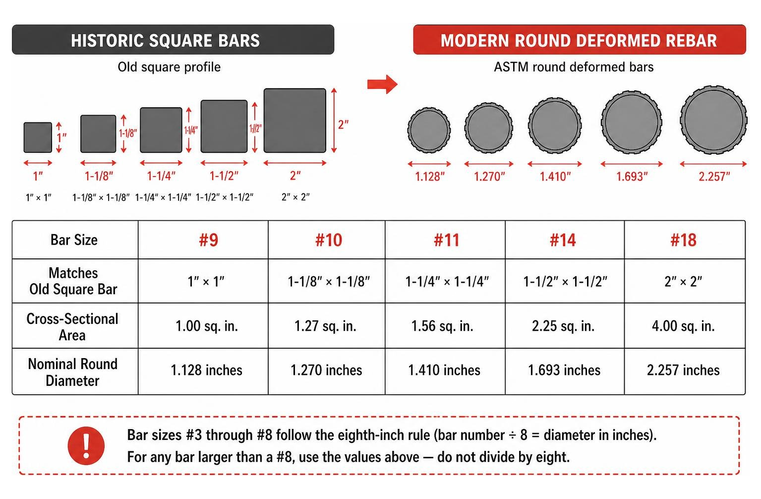
For any bar larger than a #8, always reference a verified sizing chart rather than dividing the designation by eight.
Master Reference Chart: Diameters, Areas, and Weights
Standard carbon steel rebar conforming to ASTM A615 provides predictable mechanical properties and physical dimensions across all standard grades (Grade 40, Grade 60, Grade 75, Grade 80, and Grade 100). The table below compiles the dimensional data referenced in engineering charts for U.S. construction projects.
| Bar Size (US) | Soft Metric [mm] | Nominal Diameter (in.) | Nominal Diameter (mm) | Cross-Sectional Area ($\text{in.}^2$) | Nominal Weight (lb/ft) | Nominal Weight (kg/m) |
|---|---|---|---|---|---|---|
| #3 | #10 | 0.375 | 9.5 | 0.11 | 0.376 | 0.560 |
| #4 | #13 | 0.500 | 12.7 | 0.20 | 0.668 | 0.996 |
| #5 | #16 | 0.625 | 15.9 | 0.31 | 1.043 | 1.556 |
| #6 | #19 | 0.750 | 19.1 | 0.44 | 1.502 | 2.240 |
| #7 | #22 | 0.875 | 22.2 | 0.60 | 2.044 | 3.049 |
| #8 | #25 | 1.000 | 25.4 | 0.79 | 2.670 | 3.982 |
| #9 | #29 | 1.128 | 28.7 | 1.00 | 3.400 | 5.071 |
| #10 | #32 | 1.270 | 32.3 | 1.27 | 4.303 | 6.418 |
| #11 | #36 | 1.410 | 35.8 | 1.56 | 5.313 | 7.924 |
| #14 | #43 | 1.693 | 43.0 | 2.25 | 7.650 | 11.410 |
| #18 | #57 | 2.257 | 57.3 | 4.00 | 13.600 | 20.284 |
Converting Rebar Sizes in Inches to Metric Equivalents
In structural engineering drawings that employ SI units, ASTM A615 defines “soft-metric” designations. Soft metric bars are identical in physical dimensions and weight to their imperial counterparts; they simply use the nominal diameter rounded to the nearest millimeter as the bar callout number.
For instance, a #4 bar ($0.500\text{ in.}$) is labeled as a #13 ($13\text{ mm}$), while a #8 bar ($1.000\text{ in.}$) is designated as a #25 ($25\text{ mm}$).
When evaluating international project specifications, distinguish between soft-metric ASTM callouts and true hard-metric bars (such as European EN 10080 or Canadian CSA G30.18 sizes like 10M, 15M, and 20M). A #8 U.S. bar ($25.4\text{ mm}$ diameter, $0.79\text{ in.}^2$ area) should not be confused with an $8\text{ mm}$ European tie bar, which has less than one-ninth the cross-sectional steel area.
Nominal Diameter vs. Field-Measured Caliper Dimensions
A frequent source of confusion on job sites is the difference between nominal diameter and actual field-measured diameter.
Nominal diameter represents the diameter of an equivalent, smooth, round steel bar having the identical weight and cross-sectional area per foot. Deformed reinforcing steel features raised surface deformations (ribs) designed to mechanically interlock with the cured concrete matrix.
Per standard FHWA non-destructive field inspection protocols, a caliper clamped directly across opposing transverse ribs will measure $10\%$ to $20\%$ larger than the theoretical nominal diameter. Conversely, measuring between the ribs yields a value smaller than the nominal diameter.
Inspectors verify rebar sizes by checking the raised mill identification marks rolled directly into the steel surface rather than relying solely on caliper measurements across the ribs.
Choosing the Right Bar Size by Construction Application

Selecting rebar sizes involves balancing structural load demands against concrete placement constraints. Choosing smaller bars spaced closer together can reduce surface crack widths, while larger bars streamline placement in high-load structural members. The reinforcement layout must always align with the ins and outs of rebar requirements for concrete slab construction to maintain structural integrity.
Common Bar Sizes for Residential Slabs and Footings
In residential and light commercial work, #3, #4, and #5 rebar handle the vast majority of applications:
- Patios, Walkways, and Sidewalks: Typically specify #3 rebar placed in an 18-inch to 24-inch grid. Many builders rely on using 3/8-inch rebar to prevent cracking under pressure caused by soil settlement and thermal movement.
- Residential Driveways and Garage Slabs: Standard 4-inch to 6-inch slabs commonly utilize #4 rebar ($0.500\text{ in.}$) spaced 12 to 18 inches on center. Learning how to calculate rebar for a slab properly helps avoid ordering shortfalls and ensures proper grid spacing across the pour.
- Continuous Footings and Stem Walls: Standard residential stem walls and strip footings use two to three continuous runs of #4 or #5 rebar tied with #3 stirrups to handle differential foundation loads.
Heavy Structural Applications: Beams, Columns, and Infrastructure
Commercial structures, bridges, and industrial slabs encounter substantial bending moments and axial forces, requiring heavier steel sections:
- Commercial Slabs & Grade Beams: Industrial warehouse floors often require handling 3/4-inch rebar for structural pours (#6 bar) to support heavy forklift traffic and rack post loads.
- Bridge Decks and Highway Infrastructure: Infrastructure bridge decks commonly employ #5 through #8 bars arranged in multi-layer top and bottom mats, often with epoxy or galvanized protective coatings.
- High-Rise Columns and Shear Walls: Heavy vertical columns require #9, #10, #11, or massive #14 and #18 bars bundled together to resist high compression loads and overturning seismic forces.
How to Calculate Rebar Weight and Material Takeoffs
Steel pricing, freight logistics, and crane rigging are determined by total steel tonnage rather than linear footage. Accurately estimating total rebar quantity for slab pours requires converting linear lengths into total weight.
Reinforcing bar in the United States is routinely manufactured and stocked in standard lengths:
- 20-Foot Sticks: Standard retail and residential supply length; easy to transport on standard flatbed trailers.
- 40-Foot Sticks: Standard commercial fabrication length; reduces the number of lap splices required across long runs.
- 60-Foot Sticks: Mill-direct lengths used for heavy civil and infrastructure projects to minimize connection points.
Step-by-Step Weight Calculation for Given Bar Lengths
Calculating total steel weight follows a straightforward formula:
$$\text{Total Weight (lb)} = \text{Total Length (ft)} \times \text{Nominal Weight per Foot (lb/ft)}$$
Example Calculation:
Assume an engineer’s schedule calls for thirty pieces of 20-foot-long #5 rebar for a foundation footing:
Calculate Total Linear Footage: $$\text{Total Footage} = 30 \times 20\text{ ft} = 600\text{ linear feet}$$
Identify Nominal Unit Weight: Looking up a #5 bar in the master reference chart gives $1.043\text{ lb/ft}$.
Calculate Total Steel Weight: $$\text{Total Weight} = 600\text{ ft} \times 1.043\text{ lb/ft} = 625.8\text{ lbs}$$
Adding these allowances ensures your total weight estimates match real-world material needs when ordering from fabricators.
Frequently Asked Questions About Rebar Sizes
What is the exact nominal diameter of a #4 rebar?
A #4 rebar has an exact nominal diameter of $0.500\text{ inches}$ ($1/2\text{ inch}$ or $12.7\text{ mm}$). It provides a cross-sectional area of $0.20\text{ sq. in.}$ and weighs precisely $0.668\text{ pounds per linear foot}$.
How does #5 rebar compare to #4 rebar in strength and dimensions?
While a #5 rebar ($0.625\text{ in.}$) is only $1/8\text{ inch}$ thicker in diameter than a #4 rebar ($0.500\text{ in.}$), it offers $55\%$ more cross-sectional steel area ($0.31\text{ in.}^2$ compared to $0.20\text{ in.}^2$). Because tensile capacity scales directly with cross-sectional area, a Grade 60 #5 bar can carry up to $18,600\text{ lbs}$ of yield force compared to $12,000\text{ lbs}$ for a Grade 60 #4 bar.
Can I use a caliper to verify rebar size on the job site?
Direct caliper measurements across the deformations will typically read larger than the nominal diameter because of the raised ribs. To verify bar size on site:
- Check the mill stamp rolled onto the steel (look for the bar size number between the mill symbol and steel type mark).
- Measure the round core between deformation ribs if using calipers.
- Compare the sample against a reference piece of known diameter.
Conclusion: Getting Reinforcement Sizing and Placement Right
Matching bar diameters to structural drawings is only half the battle on the job site. Even properly sized rebar will fail to protect a structure if it settles to the bottom of the pour or shifts during concrete placement. Maintaining required concrete clear cover—typically 3 inches against unformed soil and 1.5 to 2 inches for formed surfaces—is essential for long-term durability and structural safety.
At Hercules Rebar Chairs, we manufacture strong concrete support chairs engineered to keep your rebar grids locked at the exact specified height throughout the pour. Identifiable by their signature red color, our American-made supports have sold over 14 million units across all 50 states—from foundation slabs in Texas to infrastructure projects in Ohio—helping contractors maintain code compliance and save time on site.
Explore our full line of heavy-duty concrete supports and elevation chairs at Hercules Rebar Chairs to build stronger concrete on your next pour.