

Start With the Right Rebar for Foundation Layout
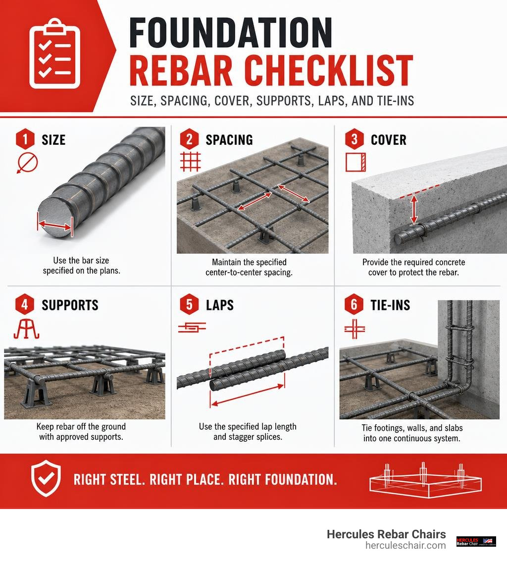
Rebar for foundation work should be chosen from the engineered plans and local code first, then installed at the right spacing, lap length, and elevation before the pour. For most residential foundations, that means using the specified bar size and grade, keeping steel off the soil with approved supports, maintaining required concrete cover, and tying the footing, wall dowels, and slab reinforcement into one continuous load path.
Rebar gives concrete the tensile strength it lacks. It helps spread building loads, control shrinkage and settlement cracks, and resist bending, uplift, and ground movement. The exact layout depends on the footing or slab design, soil conditions, frost depth, building loads, exposure to moisture or salts, and seismic requirements.
A strong foundation is not just about adding more steel. It is about placing the right steel in the right location and holding it there during concrete placement. Rebar resting on the ground, missing lap splices, poor cover, or shifted dowels can undermine an otherwise sound design.
I am Jordan Harris, a Tennessee-licensed Professional Engineer with experience designing large concrete and steel projects for power generation facilities. Today, I help develop durable support systems at Hercules Rebar Chairs, with a practical focus on making rebar for foundation work more consistent, efficient, and inspection-ready.
Understanding Rebar for Foundation Construction: Types, Sizes, and Grades
Concrete is naturally exceptional under compression. It can support thousands of pounds per square inch pressing down from above. However, its tensile strength is only about 10% of its compressive capacity. When underlying soil settles, moisture changes expand the subgrade, or structural loads create bending moments, unreinforced concrete will crack and pull apart.
Embedded reinforcing steel provides the internal backbone required to handle these tensile and shear stresses. Standard steel manufactured to ASTM A615 specifications features raised deformations (ridges) along its surface. These deformations create a tight mechanical interlock between the steel and the surrounding concrete paste, preventing slippage under heavy loads. High-quality reinforcement produced by American manufacturers like Nucor uses sustainable electric arc furnace technology, delivering high tensile performance with high recycled content.
| Rebar Material / Type | Common Foundation Uses | Tensile & Corrosion Characteristics | Relative Cost |
|---|---|---|---|
| Carbon Steel (Black Rebar) | Standard footings, stem walls, slabs | High tensile strength; susceptible to corrosion if exposed to moisture | Standard ($) |
| Epoxy-Coated Steel | High-moisture soils, coastal slabs | Protective polymer barrier; susceptible to damage during handling | Moderate ($$) |
| Galvanized Steel | Humid climates, exterior foundation walls | Zinc-coated sacrificial barrier; durable against scratching | Higher ($$$) |
| Stainless Steel | Marine foundations, chemical exposure | Forms passive chromium oxide layer; virtually rustproof | Premium ($$$$) |
| Glass Fiber Reinforced (GFRP) | Non-conductive slabs, corrosive soil | Non-metallic, high tensile capacity; cannot be field-bent | Moderate to High ($$-$$$) |
Selecting the Right Rebar for Foundation Types
Selecting the correct material type depends entirely on site exposure and environmental chemistry. Traditional carbon steel is the industry workhorse for residential and light commercial footings. For heavy residential continuous footings or commercial retaining structures, standard stock like 0.625 in x 240 in #5 Grade 60 Rebar delivers the necessary structural yield strength.
When foundations encounter high soil salinity, high groundwater tables, or deicing chemicals, standard black bar can rust over time. In coastal settings or regions with corrosive soil chemistry, epoxy-coated or hot-dip galvanized bars provide a protective shield. For specialized applications requiring complete electrical non-conductivity or total immunity to oxidation, composite fiberglass (GFRP) or stainless steel reinforcement serves as a high-performance alternative.
Decoding Rebar Sizes and Steel Grades
In the United States, standard imperial rebar designations represent the bar diameter in eighths of an inch. A #3 bar is 3/8-inch, a #4 bar is 1/2-inch, a #5 bar is 5/8-inch, and so forth up to #8 (1-inch) and beyond. For smaller footprint jobs, pre-cut bundles such as 1/2 in. x 2 ft. #4 Rebar are commonly used for short wall ties or localized stakes.
Steel rebar is also categorized by its yield strength:
- Grade 40: Minimum yield strength of 40,000 psi. Mostly limited to light residential flatwork.
- Grade 60: Minimum yield strength of 60,000 psi. The primary standard for residential and commercial foundations across the US.
- ASTM A706 (Grade 60 Weldable): Low-alloy steel specifically formulated for enhanced ductility and weldability in high seismic regions.
Mill markings stamped directly onto the bar identify its origin and properties. Reading from top to bottom, the stamp indicates the producing mill symbol, the bar size number, the steel type (“S” for carbon steel, “W” for weldable low-alloy), and the grade indicator (a “60” or a single longitudinal grade line for Grade 60).
How to Calculate Rebar for Foundation Footings and Slabs
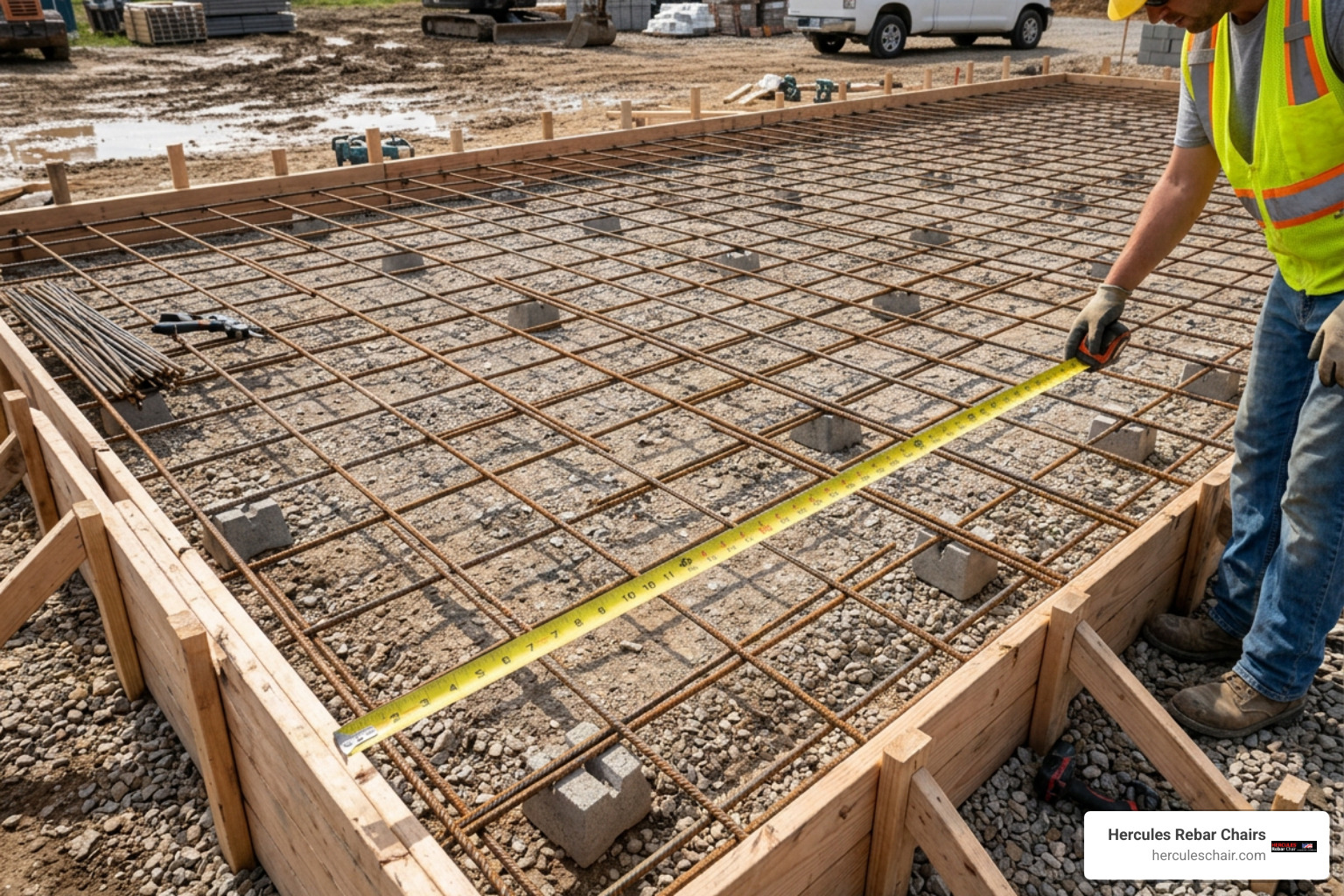
Accurate material estimation prevents mid-pour shortages and excessive scrap waste. Estimating the steel grid for a foundation slab or continuous footing begins by deducting the mandatory concrete cover from the outer dimensions to find the usable grid span.
To determine the number of bars needed across a given dimension, apply the basic grid formula:
$$\text{Number of Bars} = \left\lfloor \frac{\text{Usable Grid Length}}{\text{On-Center Spacing}} \right\rfloor + 1$$
We add “+1” because a grid requires boundary bars at both ends (the classic fence post principle). For fast automated checks and multi-element project estimating, tools like the SteelSolver Rebar Calculator or the CDCalculators Rebar Estimator help verify bar counts, total tonnage, and ACI 318 code minimums.
Calculating Lap Splices and Development Lengths
Because standard steel bars are delivered in stock lengths (typically 20 feet), foundations spanning longer distances require lap splices. A lap splice allows tensile stress to transfer smoothly from one bar to the next through the surrounding concrete paste.
Per ACI 318 standards, Class B tension lap splices typically require a lap length of 30 to 40 bar diameters for residential foundation applications (roughly 20 to 25 inches of overlap for a #4 bar and 25 to 30 inches for a #5 bar). Review our guide on how these rebar design tips help avoid common structural failures. Crucially, lap splices should always be staggered so that no more than 50% of the splices occur at the exact same cross-section of the footing or wall.
Estimating Order Quantities and Waste Factors
When finalizing a material takeoff, factor in both lap splices and cutting scrap:
- Simple Rectangular Slabs / Footings: Add a 5% to 7% waste allowance.
- L-Shaped or Irregular Foundations: Add an 8% to 10% waste allowance.
- Complex Geometries or Footings with Heavy Doweling: Add 10% to 15% to cover drop-cuts and overlaps.
To convert total linear footage into standard 20-foot sticks, divide total required linear feet (including waste) by 20 and always round up to the nearest whole bar.
Foundation Engineering: Soil, Climate, and Structural System Factors
Foundation reinforcement requirements are dictated by the geotechnical conditions beneath the trench. Expansive clay soils swell dramatically when wet and shrink when dry, subjecting footings to severe upward and downward bending moments. In northern climates, footings must sit below the local frost line to avoid frost heave, requiring deeper stem walls and robust vertical doweling. Learn more about evaluating different systems in our review of slab-on-grade foundation pros and cons. For an in-depth breakdown of engineering criteria, see RKM Homes’ foundation construction guide.
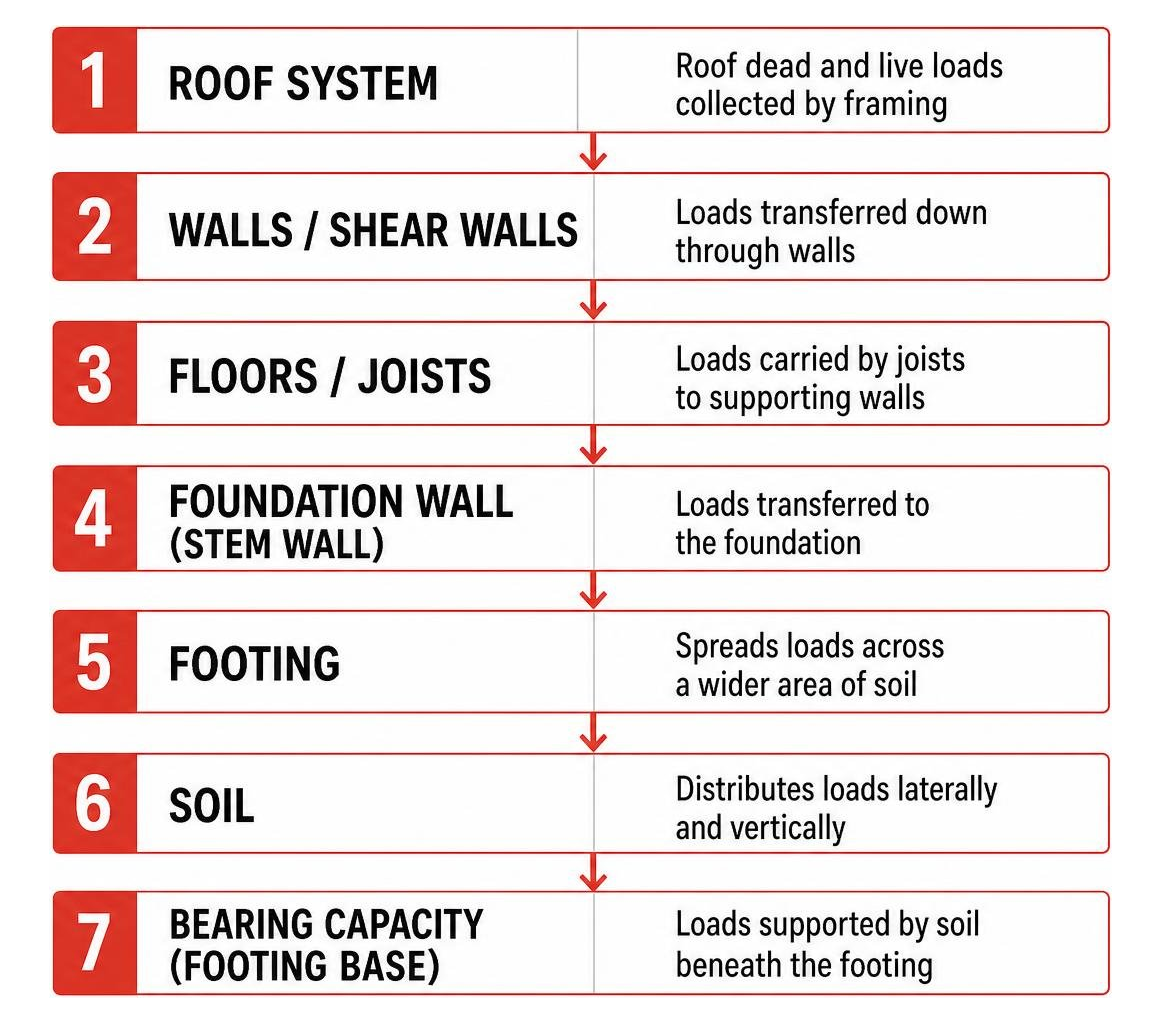
Monolithic Slabs vs. Stem Wall and Continuous Footings
Foundation construction generally falls into two categories:
- Monolithic Slabs (Turned-Down Footings): The slab and thickened perimeter footing are poured in a single continuous placement. The perimeter trench typically houses two to three horizontal runs of #4 or #5 rebar (one near the top and one or two near the bottom) to resist soil movement and edge loads.
- Stem Wall and Continuous Footings (Non-Monolithic): The footing is excavated and poured first, followed by a concrete masonry unit (CMU) or poured concrete stem wall. This assembly requires continuous horizontal footing bars combined with bent vertical dowels tied into the footing steel. For step-by-step visual configurations, review our detailed footing reinforcement details and layouts.
Seismic Code Requirements and Anchor Bolt Tie-Ins
In earthquake-prone regions—classified under the International Residential Code as Seismic Design Categories (SDC) D0, D1, and D2—unreinforced concrete foundations face catastrophic shear and uplift risks. According to the 2024 IRC Section R403.1.3, concrete footings in these zones must include vertical reinforcement of at least one No. 4 bar spaced at maximum 48-inch intervals, extending at least 14 inches into the stem wall. For detailed code interpretations, see InterNACHI’s foundation reinforcement guide.
Foundation performance during the 1994 magnitude 6.7 Northridge earthquake proved that properly reinforced foundations reduced structural damage by roughly 60% compared to unreinforced foundations. Post-earthquake data showed that repair versus replacement cost differences often exceeded $200,000 per home.
To complete this continuous load path, IRC Section R403.1.6 mandates that anchor bolts must be embedded at least 7 inches into the concrete, spaced no more than 6 feet apart (often reduced to 4 feet in high-hazard zones), and fitted with 3-inch by 3-inch by 1/4-inch steel plate washers to anchor the sill plate firmly against lateral movement.
Proper Installation, Support, and Common Mistakes to Avoid

A well-engineered rebar cage is only as strong as its physical placement in the trench. Steel must be rigidly tied at intersections using 16-gauge black annealed tie wire (using snap ties, wrap-and-snap ties, or saddle ties) so the assembly does not shift under the weight of wet concrete or workers’ boots. You can master these field procedures by following our guide on how to install rebar in footings the right way.
Achieving Mandatory Concrete Cover and Elevation
Concrete cover is the protective barrier of concrete between the outer surface of the rebar and the outside environment. Per ACI 318 Table 20.6.1.3, concrete cast permanently against and in contact with the earth—such as a foundation footing—requires a strict minimum of 3 inches (75 mm) of clear concrete cover.
Letting rebar rest on dirt, loose rocks, or scrap brick chunks violates building codes and guarantees failure. To maintain exact elevation and side clearances, always use purpose-built, non-corrosive concrete supports. Explore our in-depth resources on spacing and supporting footing rebar, consult our rebar footing stands guide, read our footer stand placement guide, and discover why cover matters in understanding concrete cover.
Critical Errors: Wet-Setting and Post-Pour Dowel Retrofits
One of the most destructive jobsite shortcuts is “wet-stabbing” or wet-setting vertical dowels into concrete after it has already been placed in the forms.

When steel is stabbed into fresh concrete, it pushes large aggregate out of the way, leaving the bar surrounded by weak, unbonded cement cream full of air voids. Furthermore, it is virtually impossible to ensure proper vertical embedment or maintain the mandatory 3-inch bottom clearance. Over time, moisture penetrates these voids, initiating rust. As steel rusts, it expands up to 600%, creating an outward hydraulic pressure known as “oxide jacking” that cracks concrete from the inside out in as few as four years.
If foundation dowels are accidentally omitted before the pour, they must be correctly retrofitted:
- Drill holes into the cured footing using a hammer drill (typically 1/2-inch to 5/8-inch diameter for #4 bar) to a minimum depth of 6 inches.
- Thoroughly blow out all concrete dust and debris using compressed air.
- Inject code-approved high-strength structural anchoring epoxy into the hole.
- Insert and twist the rebar dowel to fully encapsulate the steel.
Frequently Asked Questions About Foundation Rebar
How far apart should rebar be placed in a concrete foundation?
For residential foundation slabs and stem walls, rebar is commonly spaced between 12 and 18 inches on center in each direction. Per ACI 318-19 §24.4.3.3, maximum center-to-center spacing for non-prestressed slab reinforcement must not exceed the lesser of 3 times the slab thickness ($3h$) or 18 inches. In continuous footings, two or three continuous horizontal bars are typically spaced evenly across the footing width.
What is the minimum concrete cover required for foundation rebar?
According to ACI 318 Table 20.6.1.3:
- 3 inches: For concrete cast directly against and permanently exposed to earth (footings and trench pours).
- 2 inches: For concrete exposed to weather or earth after forms are removed (#6 through #18 bars).
- 1.5 inches: For concrete exposed to weather or earth after forms are removed (#5 bar and smaller).
- 0.75 inches to 1.5 inches: For interior slabs, beams, and enclosed building elements.
Can existing concrete slabs be retrofitted with rebar?
Existing slabs cannot have internal rebar grids cast into them retroactively. However, existing foundations can be structurally retrofitted by installing post-drilled dowels anchored with structural epoxy, underpinning perimeter footings with reinforced grade beams, or installing foundation anchor plates and hold-downs to meet current seismic performance standards.
Conclusion
A durable concrete foundation relies on high-quality steel, accurate spacing calculations, proper lap lengths, and uncompromised concrete cover. Cutting corners on rebar support or skipping pre-pour inspections can lead to costly structural repairs down the road.
At Hercules Rebar Chairs, we have supplied over 14 million high-strength, code-compliant concrete supports across all 50 states to keep rebar stable and perfectly elevated during heavy pours. Take time to verify your rebar layout before calling the concrete truck, execute a thorough pre-pour checklist, and ensure long-term durability by mastering rebar placement for lasting concrete.