

How to Get Footing Rebar Layout Right
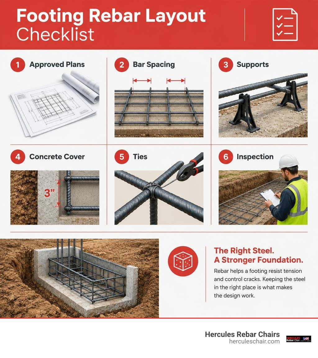
For a reliable footing rebar layout, start with the approved plans. Check the bar size, number of bars, and spacing. Set the steel on supports so it stays in place during the pour, and keep at least 3 inches of concrete between the rebar and any surface cast against earth. Tie the bars, check the specified overlaps and wall dowels, then inspect the layout before concrete covers it.
The key is keeping the steel where the design calls for it. Rebar helps a footing resist tension and control cracks, but bars that shift or touch the soil cannot do their job as intended.
I’m Jordan Harris, a Tennessee-licensed structural engineer who spent five years working on large concrete and steel projects. I bring that experience to footing rebar layout and to the rebar supports we make at Hercules Rebar Chairs.
Fundamentals of Concrete Footing Reinforcement and Material Selection
Concrete is an incredible building material when you press down on it. It can easily carry massive compressive loads, but it behaves very differently when pulling, bending, or stretching forces come into play. Soil settlement, frost heave, and dynamic structural loads create bending moments across foundation footings. Without steel reinforcement to handle these internal tensions, standard concrete cracks and fails long before reaching its design lifespan.
Meeting ASTM A615 specifications for deformed carbon-steel bars ensures your foundation has the ductile strength required to transfer structural loads smoothly into the earth.
Why Concrete Needs Steel Reinforcement
Concrete’s tensile strength is only about 10% of its compressive strength. When a home settles or experiences uneven soil bearing, the bottom of the footing is pulled outward in tension while the top is compressed. Unreinforced concrete cannot stretch; it snaps, causing diagonal shear cracks that travel straight up into your stem walls and framing.
Concrete loses up to 35% of its strength without proper rebar placement. Steel reinforcement absorbs these tensile forces, controls crack propagation, and distributes concentrated wall loads over a broader soil footprint. For anyone starting out, reviewing our beginners guide to rebar for footer requirements clarifies how structural load paths depend on tension steel working in tandem with concrete.
Selecting the Right Rebar Grade, Coating, and Size
Choosing the appropriate rebar grade, coating, and size depends directly on your structure’s weight, soil chemistry, and environmental exposure. Grade 60 steel (yielding 60,000 psi) represents the industry benchmark for standard foundation engineering.
| Rebar Type | Corrosion Resistance | Common Project Use | Relative Cost |
|---|---|---|---|
| Grade 60 Carbon Steel (Black Rebar) | Baseline standard | Standard residential footings & dry soils | Budget-friendly |
| Epoxy-Coated Rebar | Up to 1,700x greater than carbon steel | Coastal areas, high water tables, deicing salts | Moderate |
| Galvanized Rebar | ~40x better than carbon steel (50–100 yr life) | Industrial footings, humid soils, exposed slabs | Moderate to High |
| Stainless Steel Rebar | ~1,500x greater than carbon steel | Critical infrastructure, extreme chemical exposure | Premium |
| GFRP (Fiberglass Rebar) | 100% rust-proof (non-metallic) | MRI rooms, electrical substations, marine walls | Moderate to High |
For typical residential continuous footings, #4 rebar (1/2-inch nominal diameter) is standard. Larger structures, multi-story commercial projects, or footings placed on soils with bearing capacities under 1,500 psf often specify #5 (5/8-inch) or #6 (3/4-inch) bars to resist higher bending stresses.
Engineering a Code-Compliant Footing Rebar Layout
A durable foundation requires strict alignment with structural engineering drawings and regional codes. The International Residential Code (IRC) and American Concrete Institute (ACI 318) define clear geometric minimums. Most residential building codes establish a baseline dimension of at least 12 inches wide and 6 inches thick for footings beneath load-bearing walls, though local soil conditions frequently dictate wider footing trenches.
Code Mandates and Spacing Rules for a Footing Rebar Layout
Spacing your reinforcement correctly ensures concrete aggregates flow freely around each bar while providing the required tensile steel area. Designers use tools like a Rebar Spacing Calculator and ACI 318 design rules to confirm that the layout stays within flexural code boundaries.
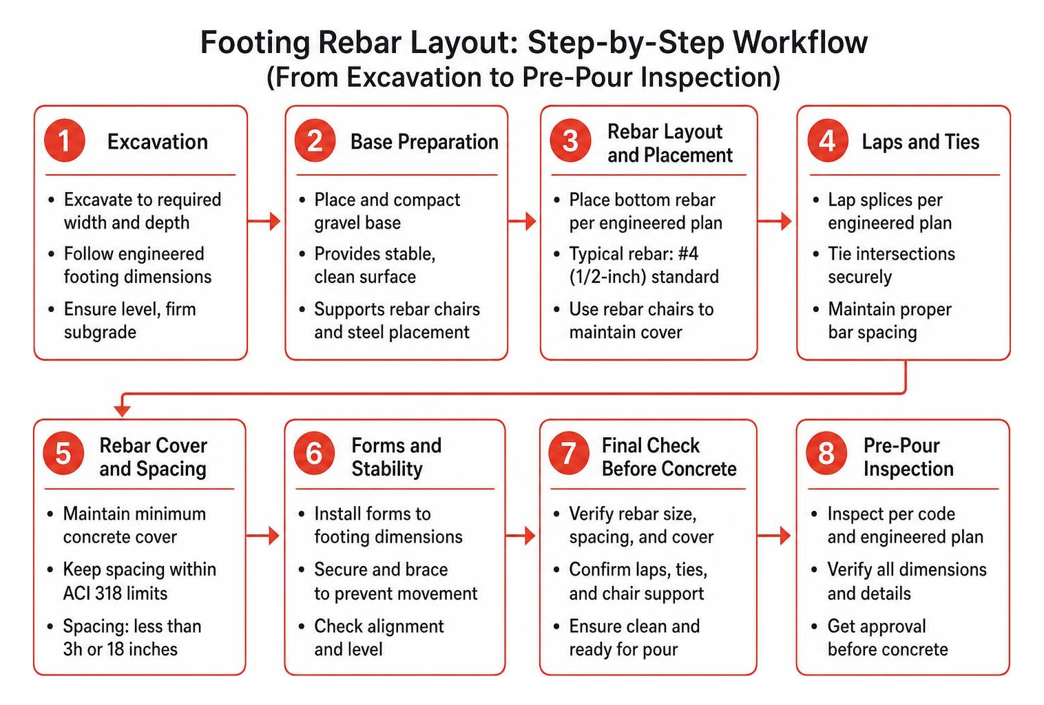
Under ACI 318-19, flexural reinforcement spacing in footings cannot exceed the lesser of three times the footing thickness (3h) or 18 inches. Temperature and shrinkage reinforcement follows the 5h rule (up to an 18-inch maximum).
Clear spacing between parallel bars must always equal or exceed the largest of three conditions:
- 1.5 times the nominal bar diameter
- 1.5 inches
- 1.33 times the maximum coarse aggregate size
Maintaining clear distance prevents “honeycombing,” where rock gets trapped between bars and leaves air pockets. Never ignore your concrete cover: codes require 3 inches of clear concrete cover when footings are cast directly against unformed earth, and 2 inches when concrete is poured inside forms. Following proven step-by-step footing reinforcement details and layouts keeps every bar aligned with these legal structural limits.
Seismic Design and High-Load Requirements
Building in Seismic Design Categories (SDC) D0, D1, and D2 calls for extra reinforcement to prevent structural separation during seismic events. As detailed in the IRC Chapter 4 foundation reinforcement provisions, footings in these zones require continuous longitudinal steel and vertical connection dowels.
In high seismic zones, vertical reinforcement must include at least one #4 bar placed at intervals no greater than 48 inches on-center, extending from the footing into the stem wall with standard hooks. The historical necessity of these mandates was proved during the 1994 Northridge earthquake: properly reinforced foundations reduced structural damage by roughly 60% compared to unreinforced concrete bases. Because post-earthquake foundation replacements frequently exceeded $200,000 per home, investing in a robust seismic tie-down layout provides essential protection for both building and budget.
Step-by-Step Execution for Trench and Pad Footings
Setting up a footing requires accurate site prep before any steel enters the trench:
- Establish Layout Lines: Set up batter boards and string lines beyond the excavation perimeter.
- Square the Corners: Use the 3-4-5 squaring rule (measuring 3 feet along one leg, 4 feet along the other, and adjusting until the hypotenuse measures 5 feet) to confirm clean 90-degree corners.
- Excavate Below Frost Depth: Dig down past your local frost line into undisturbed native soil.
- Level the Base: Scrape loose soil out of the trench and compact a solid gravel base.
Continuous Trench Footings vs. Isolated Pad Footings
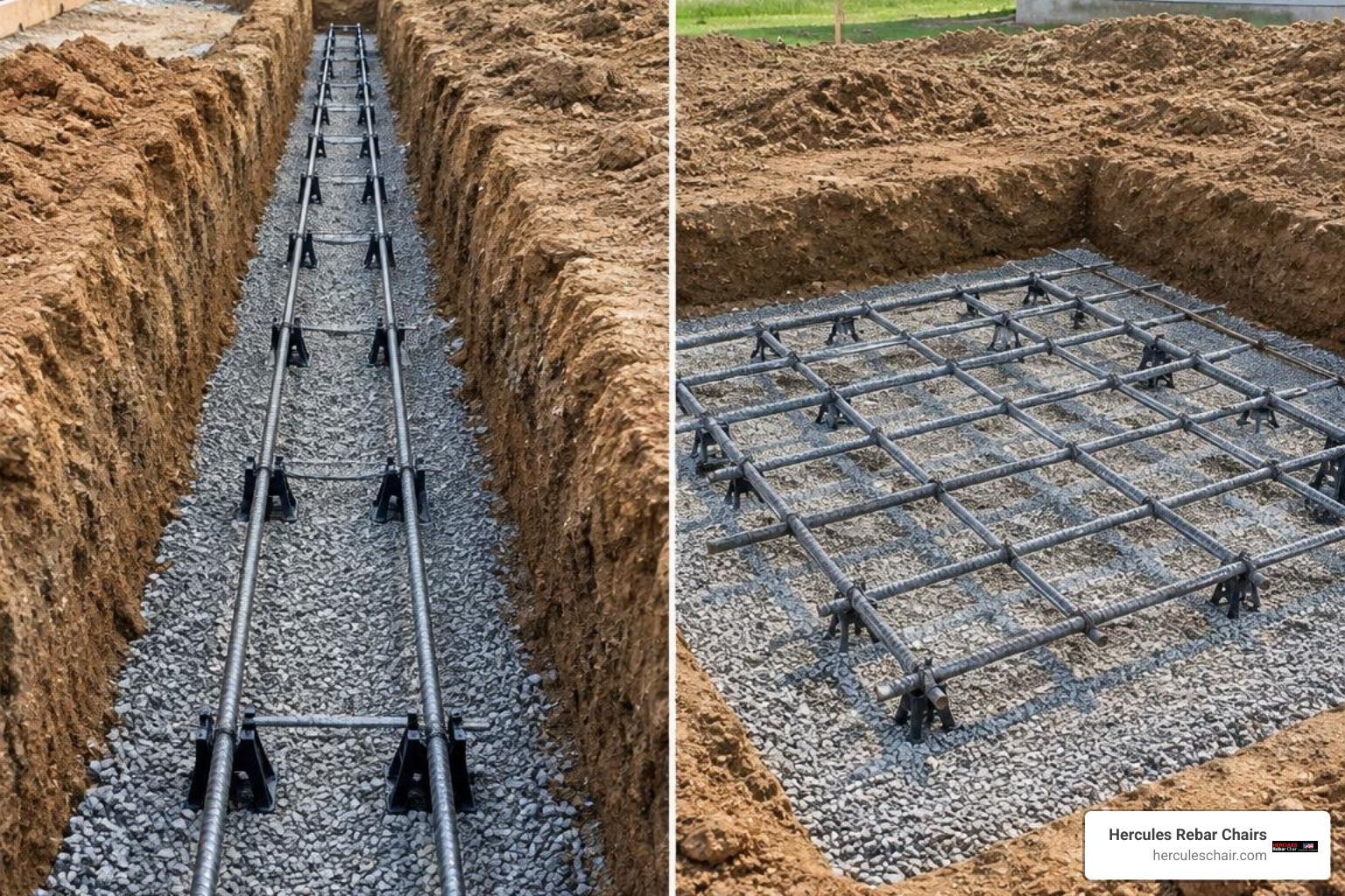
A typical residential home produces 1,000 to 2,000 pounds of load per linear foot of wall. A continuous strip footing distributes this continuous linear load along the entire perimeter. These trenches typically feature two or three parallel lines of continuous longitudinal rebar suspended near the bottom third of the footing thickness. Supporting these runs with a purpose-built 2-bar footer stand locks parallel bars into place at uniform spacing without hand measurements in the trench.
Isolated pad footings, by contrast, support concentrated point loads from central posts, columns, or deck piers. Instead of linear runs, isolated pads require a two-way rebar grid (often referred to as a rebar mat). Bars run perpendicular to one another in both directions, tied at intersections to create a stable cage that counters intense two-way punching shear.
Calculating Materials and Splice Lengths for Your Footing Rebar Layout
Ordering rebar requires calculating both net linear runs and the steel needed for overlapping splices. You can follow a practical builder guide on calculating rebar quantities to build reliable estimates.
The basic linear footage formula for a continuous trench is:
Total Linear Footage = (Total Trench Perimeter × Number of Parallel Bars) + Lap Splices + Corners + Waste Factor
When joining two bars end-to-end, the standard tension lap splice length is calculated as 40 times the bar diameter (40d):
- #3 Rebar (3/8″): 40 × 0.375 in = 15-inch lap
- #4 Rebar (1/2″): 40 × 0.500 in = 20-inch lap
- #5 Rebar (5/8″): 40 × 0.625 in = 25-inch lap
Always add a 10% to 15% waste buffer to account for corner bends, dowel cutoffs, and field adjustments. To calculate delivery weight, standard #4 rebar weighs 0.668 pounds per linear foot. For example, a 1,375 linear foot order of #4 rebar equals roughly 919 pounds of steel.
Practical Placement, Tying Techniques, and Support Guidelines
The best rebar calculations mean little if steel shifts during concrete placement. Shifting rebar by just half an inch in a 6-inch footing slab can reduce its structural load-carrying capacity by 20%.
Elevating Steel with Footer Stands and Chairs

Rebar cannot sit on the ground, on loose dirt mounds, or on scrap bricks. When steel touches soil, ground moisture migrates directly into the metal. When carbon steel rusts, it expands by 2 to 3 times its original volume, exerting internal pressure that cracks and spalls surrounding concrete from the inside out.
We manufacture our bright red Hercules Rebar Chairs to solve this problem permanently. With over 14 million units sold across the United States, our footer chairs are engineered to hold rebar firmly at the exact code-mandated 3-inch clearance off the trench floor.
Place supports every 3 to 4 feet along the trench to eliminate bar sagging under heavy wet concrete. Reviewing our guides on how to install rebar in footings the right way and our footer stand placement guide will help your crew set stable support layouts that pass pre-pour inspections every time.
Secure Tying Methods and Avoiding Costly Mistakes
Tying rebar locks the steel frame into a rigid unit that resists displacement from concrete chutes and vibrators. Use 16-gauge annealed steel tie wire and pair the right tie knot to the joint:
- Snap Tie (Single Tie): The quickest tie for flat grid intersections on isolated pads.
- Saddle Tie (U-Tie): Ideal for continuous runs where parallel bars sit in cradle stands; wire loops under the support, crosses over the bar, and twists tight.
- Figure-Eight Tie: Used on heavy corner transitions and vertical dowels where joint slippage must be prevented.
Avoid these common layout pitfalls:
- Never stick vertical dowels into freshly poured concrete (“wet setting”). Dowels must be tied securely to the footing rebar cage before the pour starts.
- Always bend rebar around corners rather than stopping bars at the turn; use pre-bent 90-degree corner bars that overlap the straight runs by at least 40 bar diameters.
- Keep rebar clean and free of loose mud, excessive flaking rust, or oil so the concrete paste bonds directly to the bar deformations.
Our detailed breakdown on keeping a rebar layout for concrete footings made simple and code compliant walks through field-tested ways to prevent these mistakes.
Frequently Asked Questions About Footing Rebar Layout
What is the minimum concrete cover required for rebar in footings?
Under ACI 318 Section 20.6.1.3 and residential building codes, concrete cast directly against earth with no formwork requires a minimum of 3 inches of clear concrete cover on all bottom and side surfaces. If the footing is poured into forms (such as wood or metal edge forms), the required minimum clear cover is 2 inches. This protective concrete layer shields internal steel from soil-borne moisture, chlorides, and premature corrosion.
How do you calculate the correct lap splice length for footing rebar?
The standard rule of thumb for footing tension splices is 40 bar diameters (40d). For common #4 (1/2-inch) rebar, multiply 40 by 0.5 inches to arrive at a 20-inch minimum overlap. For #5 (5/8-inch) rebar, the minimum splice is 25 inches. Splices should be tied securely with wire in at least two places across the overlap zone.
Can you place rebar directly on the ground or gravel before pouring?
No. Placing rebar directly on dirt, rocks, gravel, or temporary wood scraps violates building codes across the country. Steel placed on the ground ends up with zero bottom concrete cover, leaving the metal exposed to groundwater. Over time, moisture causes steel oxidation, expanding the metal by 2 to 3 times its volume and causing the footing concrete to delaminate and crack. Rebar must always be elevated and stabilized on code-compliant concrete chairs or footer stands.
Conclusion
A solid, level structure starts with a properly planned and supported footing rebar layout. By matching steel sizing to structural loads, calculating accurate lap splices, and elevating reinforcement with durable chairs, you build foundations that withstand dynamic soil pressures, seismic stresses, and environmental moisture.
At Hercules Rebar Chairs (T.J. Harris Co.), we make code compliance simple. Our distinct red footer chairs have supported more than 14 million concrete reinforcement layouts across America, saving crews time and preventing costly structural re-work.
To master foundation layout and chair spacing for your next project, read the ultimate guide to spacing and supporting footing rebar and build your foundations on a base that never bends under pressure.