

Fundamentals of Rebar for Footer Design and Strength
Standard residential foundations typically require installing rebar for footer support using two continuous parallel runs of #4 (1/2-inch) Grade 60 steel elevated a minimum of 3 inches above the trench floor with 40-diameter (20-inch) lap splices. While concrete delivers exceptional compressive strength under downward building loads, reinforcing steel provides the essential tensile capacity needed to resist soil movement, frost heave, and uneven settlement.
When soil shifts, moisture fluctuates, or building weight bears down unevenly, the footing experiences intense bending moments. Without steel reinforcement placed in the lower third of the concrete section where tension peaks, footings develop vertical stress cracks that quickly compromise the entire structure. Understanding the fundamental step by step footing reinforcement details and layouts gives builders the framework necessary to prevent foundation failure before concrete ever enters the trench.
Why Footings Require Reinforcing Steel
Every structure exerts dead loads (the weight of the building itself) and live loads (occupants, furniture, wind, and snow). These forces travel through load-bearing walls down into the footing, which must spread the load evenly across the ground.
When expansive clays swell, freeze-thaw cycles create frost heave, or subgrades settle unevenly, the ground exerts upward or localized downward forces known as differential settlement. Reinforcing steel bridges these soft spots, transforming the footing into a continuous structural beam.
Under the American Concrete Institute (ACI 318-19) building standards, steel reinforcement also controls temperature shrinkage and crack propagation. As concrete cures, it loses moisture and naturally shrinks. Rebar distributes these internal tensile stresses evenly across the assembly, keeping micro-fissures from expanding into structural fractures.
Selecting the Right Rebar for Footer Construction by Bar Size
Standard US reinforcing steel is categorized by imperial bar numbers representing the diameter in eighths of an inch. Grade 60 steel (yielding 60,000 psi) represents the industry standard across all modern residential and light commercial work.
| Rebar Size | Nominal Diameter (in.) | Cross-Sectional Area (sq. in.) | Unit Weight (lb./linear ft.) | Common Footing Applications |
|---|---|---|---|---|
| #3 | 0.375 (3/8″) | 0.11 | 0.376 | Light slab mesh, stirrups, non-bearing ties |
| #4 | 0.500 (1/2″) | 0.20 | 0.668 | Standard residential continuous strip footings |
| #5 | 0.625 (5/8″) | 0.31 | 1.043 | Heavy two-story builds, poor soil, commercial pads |
| #6 | 0.750 (3/4″) | 0.44 | 1.502 | Multi-story structures, high-capacity column footings |
| #7 | 0.875 (7/8″) | 0.60 | 2.044 | Heavy commercial and civil foundation mats |
| #8 | 1.000 (1″) | 0.79 | 2.670 | Industrial heavy equipment pads and bridge piers |
For light single-story residential projects on stable ground, #4 rebar provides the optimal balance of strength, workability, and cost. When transitioning to heavier multi-story builds, weak bearing soils, or high-load column bases, upgrading to #5 or #6 rebar delivers the required tensile capacity.
Footing Dimension Rules of Thumb and Sizing Ratios
A standard rule of thumb for residential strip footings is that the footing width should equal roughly twice the width of the wall it supports, while the footing depth (thickness) should equal the wall thickness. For example, an 8-inch concrete stem wall generally calls for a 16-inch wide by 8-inch deep footing.
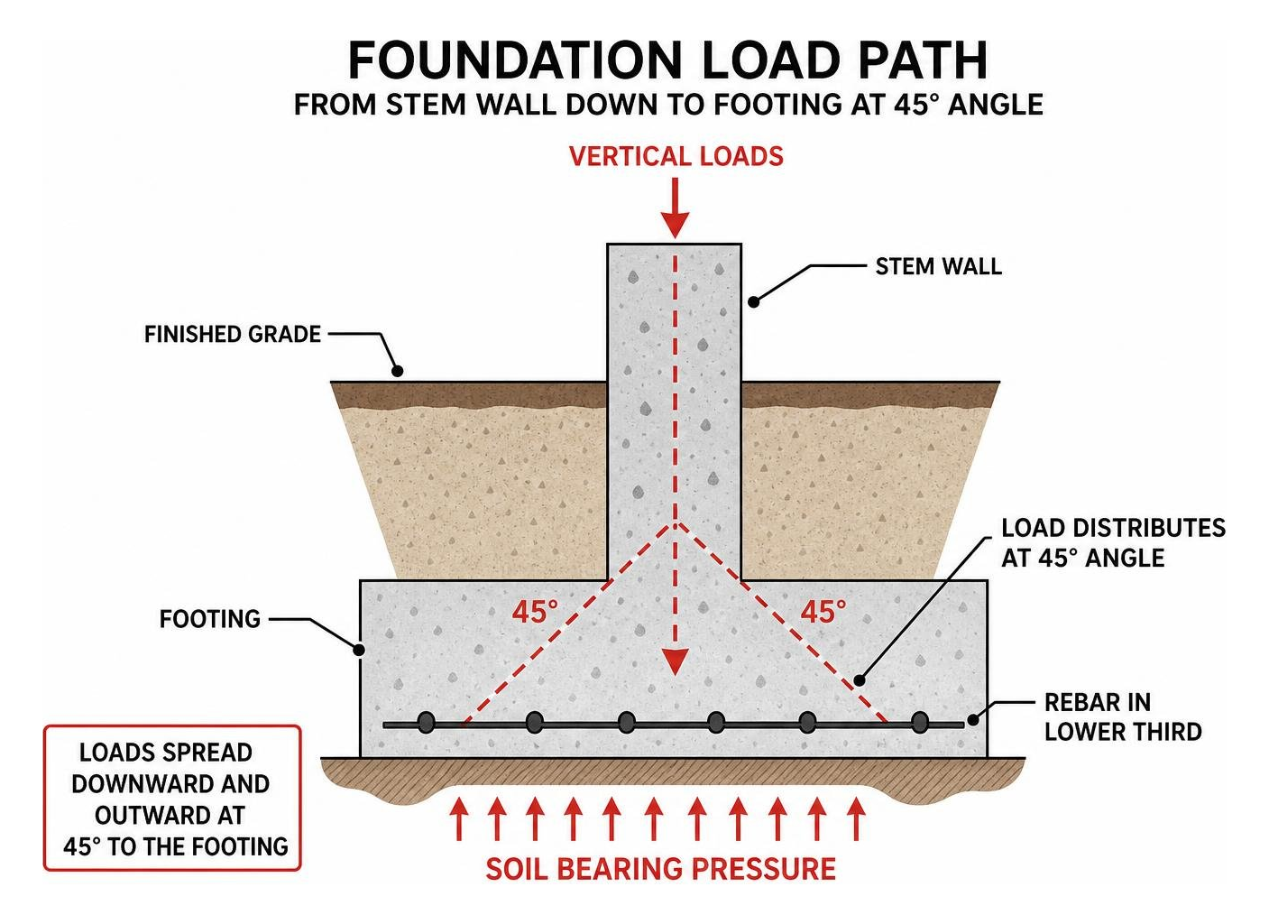
Regardless of width, the absolute prescriptive minimum footing thickness under standard residential building codes is 6 inches. Load distributes downward from the wall through the footing at roughly a 45-degree angle. If a footing is poured too wide without sufficient thickness or adequate rebar, the unsupported outer edges can snap upward under heavy loads. Following a step by step guide to determine rebar requirements for foundation plans ensures dimensions and steel configurations match the exact soil conditions on your jobsite.
Building Codes, Soil Dynamics, and Seismic Zone Requirements
Foundation engineering involves strict compliance with regional building codes like the International Residential Code (IRC Section R403) and state adaptations such as the CHAPTER 4 FOUNDATIONS – 2022 CONNECTICUT STATE BUILDING CODE. These regulatory standards govern minimum dimensions, steel specifications, and embedment depths to ensure public safety.
Soil Bearing Capacity and Differential Settlement Mitigation
Soil bearing capacity measures how much pressure (in pounds per square foot, or PSF) the ground can safely hold without settling. Most residential prescriptive codes benchmark standard design on a presumed soil capacity of 1,500 to 2,000 PSF.
If a geotechnical report reveals expansive clay, loose fill, or high water tables, standard soil assumptions no longer apply. Expansive clay swells dramatically when wet and contracts when dry, creating vertical movement that snaps unreinforced footings. Continuous longitudinal steel reinforcement turns the footing into a rigid structural ring, distributing point loads across the entire footprint to bridge localized weak spots.
High-Wind and Seismic Design Category Reinforcement Rules
In regions classified under Seismic Design Categories (SDC) D0, D1, and D2—or coastal high-wind zones—reinforcement codes become significantly more stringent.
Under IRC Section R403.1.3 and state provisions like the Chapter 4 Foundations: Arkansas Residential Code 2021, continuous footings in high-seismic zones must incorporate:
- Vertical reinforcement consisting of at least one #4 bar spaced at a maximum of 48 inches on center.
- Vertical bars embedded with standard hooks terminating within the lower section of the footing and extending a minimum of 14 inches up into the stem wall.
- One continuous horizontal #4 bar positioned within 12 inches of the top of the stem wall and another within 3 to 4 inches of the bottom of the footing.
Similarly, coastal and hurricane zones—such as North Carolina high-wind areas—mandate footings reinforced with three #4 bars or two #5 bars positioned 3 inches above the trench bottom to counteract uplift forces and overturning moments.
Unreinforced Plain Footings vs. Reinforced Concrete Requirements
In some jurisdictions with ideal, undisturbed soil and low seismic hazard ratings (Categories A, B, and C), building codes allow unreinforced “plain concrete” footings for light, single-story structures.
However, relying on plain concrete leaves a structure vulnerable. If an undetected soft soil pocket, plumbing leak, or frost heave event occurs beneath the home, an unreinforced footing cracks completely through. Adding reinforcing steel costs a small fraction of the total build, making it the most cost-effective insurance policy available. Reviewing practical structural tips like dont let your foundation fail with these rebar design tips will keep your foundation intact through unexpected subgrade shifts.
Placement Standards, Spacing, and Support Installation
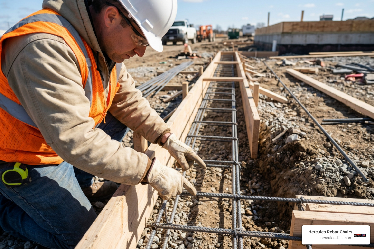
Steel provides zero tensile benefit if it rests on the bottom of the trench or shifts out of place during the pour. Proper steel installation requires strict adherence to clear cover rules, secure wire ties, and stable elevation chairs. Following professional guidelines on how to install rebar in footings the right way guarantees that the steel remains locked in place when the concrete hose starts pumping.
Concrete Clear Cover and Support Elevation
“Concrete cover” refers to the thickness of solid concrete between the outer surface of the rebar and the outer edge of the element.
Per ACI 318 Table 20.6.1.3 and IRC R403.1.3.1:
- Concrete cast against and permanently exposed to earth: Requires a minimum of 3 inches of clear cover on the bottom and sides.
- Concrete formed with wood/steel and exposed to weather: Requires a minimum of 2 inches of clear cover (#6 through #18 bars) or 1.5 inches (#5 bars and smaller).

When steel lacks adequate clear cover, moisture penetrates the porous concrete. The carbon steel oxidizes and rusts, expanding up to 600% of its original volume. This internal pressure creates spalling, cracking the concrete off from the inside out.
To maintain this vital 3-inch clearance, never prop rebar on scrap brick, wood scraps, or loose rocks, which absorb moisture and create direct leak paths. Instead, explore the ultimate guide to footer stand options to choose dedicated chairs and stands that hold bars securely off the trench subgrade.
Center-to-Center Bar Spacing and Grid Alignment
For continuous residential strip footings, two parallel runs of #4 or #5 rebar represent the standard configuration. Footings up to 24 inches wide generally use two parallel lines spaced 12 inches on center, ensuring a 3-inch clear margin from each trench wall.
For wide footing trenches (24 inches or wider) or square column pads, steel is arranged in a two-way criss-cross grid. Per ACI 318-19 §24.4.3.3, maximum center-to-center bar spacing for nonprestressed elements must not exceed the lesser of 3 times the footing thickness (3h) or 18 inches. For a comprehensive look at setting proper bar gaps, check out the ultimate guide to spacing and supporting footing rebar.
Monolithic Slab Footings vs. Non-Monolithic Stem Wall Assemblies
Foundation design generally follows one of two common paths:
- Monolithic Slabs (Turned-Down Footings): The slab floor and perimeter footer are poured simultaneously in a single, continuous pour. Rebar consists of horizontal perimeter runs enclosed by vertical hairpin stirrups or continuous bent dowels. Learn more about the structural dynamics of this system by reviewing the pros and cons of slab on grade foundations.
- Non-Monolithic Assemblies (Independent Footing and Stem Wall): The footing is poured first as a flat strip. Vertical L-shaped dowels are embedded into the wet concrete to tie into the future stem wall or masonry block assembly. This prevents lateral sliding along the cold construction joint.
Calculating Rebar for Footer Layouts and Material Takeoffs
Accurate material estimation ensures your job site has sufficient steel on pour day without over-ordering expensive excess stock.
Continuous Trench vs. Isolated Pad Footing Formulas
To calculate steel for a continuous strip footing:
$$\text{Total Base Footage} = \text{Trench Perimeter (ft)} \times \text{Number of Parallel Runs}$$
Example: A 120-foot perimeter continuous trench with 2 runs of #4 rebar:
$$\text{Base Footage} = 120 \times 2 = 240 \text{ linear feet}$$
To calculate steel for an isolated square column pad:
- Deduct 3 inches of clear cover from each side: $\text{Grid Length} = \text{Pad Dimension} – 6\text{ inches}$.
- Determine bar count per direction using the formula $N = \lfloor\frac{\text{Grid Length}}{\text{Spacing}}\rfloor + 1$.
- Multiply bar count by grid length and by 2 (for both directions).
Lap Splice Lengths and Waste Factor Calculations
Because rebar ships in standard 20-foot stick lengths, running long footing perimeters requires overlapping bars side-by-side. This overlapping section is called a lap splice.
The standard residential rule for tension lap splices is 40 times the bar diameter ($40d$):
- #4 Rebar (0.50 in. diameter): $40 \times 0.50\text{ in.} = \mathbf{20\text{ inches minimum lap splice}}$
- #5 Rebar (0.625 in. diameter): $40 \times 0.625\text{ in.} = \mathbf{25\text{ inches minimum lap splice}}$
For continuous footing estimates, adding a 10% to 15% waste and splice buffer covers all lap overlaps, corner bends, and cut ends.
$$\text{Final Order Quantity} = 240 \text{ LF} \times 1.10 = \mathbf{264 \text{ linear feet (14 sticks of 20-ft rebar)}}$$
For instant digital verification, you can check your dimensions using tools like the Rebar Calculator: Bars, Spacing, Weight & Cost – Calculator Academy or explore How to Calculate Rebar for Footings: A Complete Builder’s Guide | ProBuilderCalc alongside the structural formulas in the Rebar Calculator – Quantity, Spacing & Weight Estimator | ACI 318.
Weight Takeoffs and Project Cost Considerations
Steel suppliers sell rebar by weight (hundredweight or tons). To calculate total order weight, multiply total linear footage by the unit weight constant:
$$\text{Total Weight (lbs)} = \text{Total Linear Feet} \times \text{Weight per Foot (lb/ft)}$$
For 264 linear feet of #4 rebar ($0.668\text{ lbs/ft}$):
$$\text{Total Weight} = 264 \times 0.668 = \mathbf{176.35 \text{ lbs}}$$
A standard residential strip footing project generally ranges from $5 to $15 per linear foot for materials and installation, bringing a typical residential foundation footing package to roughly $500 to $2,500 depending on regional labor, excavation depth, and steel pricing.
Installation Best Practices and Costly Mistakes to Avoid
The strongest structural blueprints mean nothing if field installation is sloppy. Avoiding common placement mistakes protects your project timeline, prevents costly inspection rejections, and ensures decades of structural stability.
Subgrade Preparation and Dirt Contact Prevention
Before placing rebar, make sure the trench floor is clear of loose spoils, standing water, and organic debris. Excavate down to solid, undisturbed subgrade.
Never push rebar down into wet concrete after it is poured (“wet-setting”), and never lay steel directly on dirt. Wet-setting leads to inconsistent embedment depths, while steel resting on soil quickly corrodes. To keep steel perfectly positioned during the pour, install chairs at standard intervals by following our footer stand placement guide.
Corner Detailing, Splicing Errors, and Dowel Misalignment
Foundation corners experience concentrated structural stresses. Straight rebar terminating abruptly at a corner creates a hinge point that invites cracking.
- Corner Continuity: Always bend continuous bars around 90-degree corners or splice pre-bent L-shaped corner bars (with full 40d laps in both directions).
- Splice Security: Tie every lap splice tightly in at least two places using 16-gauge steel tie wire to prevent bars from shifting under the weight of the concrete pour.
- Dowel Centering: Ensure vertical stem wall dowels are tied securely to the lower horizontal footing cage so they do not drift off-center when concrete is placed.
Frequently Asked Questions About Footing Rebar
What is the standard rebar size for a residential footer?
The standard reinforcement for standard single- and two-story residential footings is #4 rebar (1/2-inch diameter). If the structure is three stories, carries heavy concentrated loads, or sits on weak soil (below 1,500 PSF bearing capacity), engineers generally upgrade specifications to #5 rebar (5/8-inch diameter). You can reference specific regional adaptations such as the Chapter 4 Foundations: Alabama Residential Code 2015 or sizing guidance in the Rebar Size & Spacing Guide for Concrete Footings.
How far off the ground should rebar be in a footing?
Rebar cast directly against earth must have a minimum of 3 inches of clear concrete cover beneath and alongside it per ACI 318 Table 20.6.1.3. This requires elevating the rebar 3 inches off the trench floor using code-compliant support chairs.
Can you pour concrete footings without rebar?
While plain unreinforced footings are technically permitted by prescriptive residential codes in select regions with high soil bearing capacities and low seismic risk, omitting steel is strongly discouraged. Steel reinforcement provides critical tensile strength, prevents differential settlement cracks, and protects your foundation investment against unexpected ground movement.
Conclusion
Building a strong concrete foundation requires the right materials, accurate sizing calculations, and strict code compliance. By maintaining a 3-inch clear cover, securing 40d lap splices, and positioning your steel on stable supports, you ensure your foundation will stand firm for generations.
At Hercules Rebar Chairs (T.J. Harris Co.), we make code-compliant steel placement fast, simple, and reliable. Proudly recognized as America’s #1 rebar support manufacturer with over 14 million units sold, our signature red chairs are engineered to hold your steel firmly in place during the most demanding pours.
Ready to streamline your next footing project while saving time and labor? Explore our heavy-duty 2 bar footer stand today to elevate your foundation with total confidence!