

When Does a Footing Need Rebar?
Not every concrete footing needs rebar. The requirement depends on the approved plans, local code, soil conditions, building loads, and seismic risk. When rebar is required, check the specified bar size and layout, then support the bars so they stay in place with the required concrete cover during the pour. Do not assume that two bars or 12-inch spacing fits every footing.
Concrete carries weight well, but it can crack when it bends or stretches. Rebar helps a footing resist those forces. Good placement matters as much as having the right steel.
I’m Jordan Harris, a Tennessee-licensed structural engineer with five years of experience designing large concrete and steel structures. Today, I help develop rebar supports at Hercules Rebar Chairs, bringing that engineering background to practical questions about rebar for footing work.
The Critical Structural Role of Foundation Reinforcement
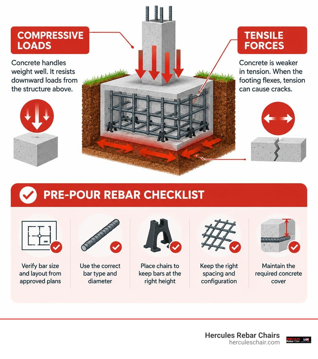
A solid home starts with the interaction between concrete and the earth below it. Concrete demonstrates exceptional compressive strength—often specified at 3,500 psi or higher per American Concrete Institute (ACI 318) guidelines. It easily handles downward structural loads from framing, roofs, and live loads. However, concrete’s tensile strength is only about 10% of its compressive capacity. When underlying soil settles or frost expands underneath, the footing flexes. Without steel reinforcement, tension quickly causes structural cracking.
Essential Functions of Rebar for Footing Support and Crack Prevention
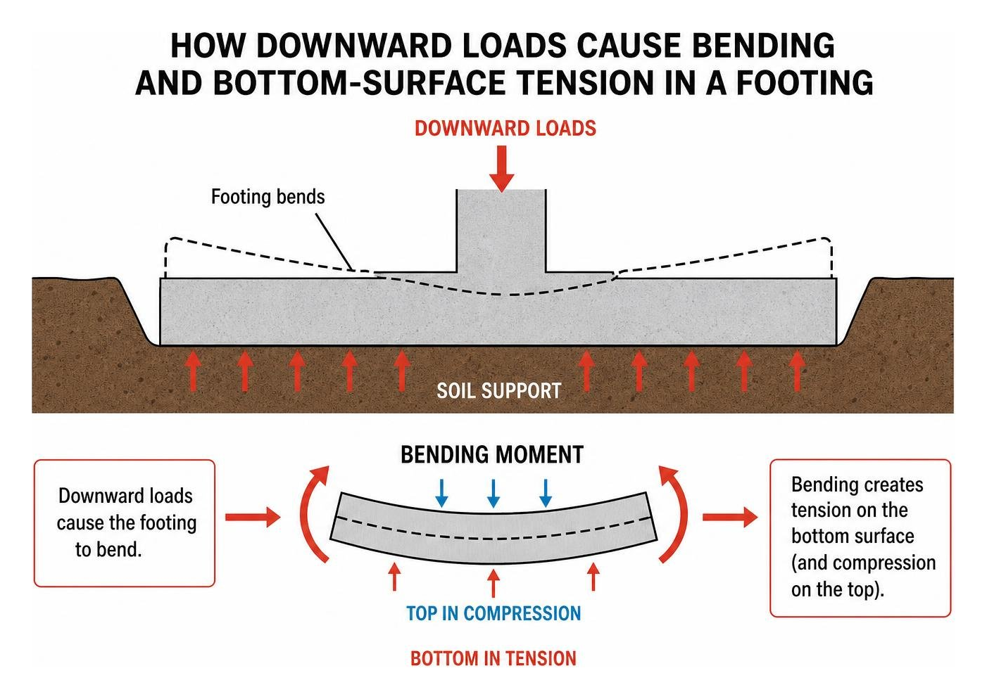
When a foundation shifts, bending stresses generate tension along the bottom or top of the footing. Reinforcing steel carries these tensile loads, bridging weak spots in the earth and controlling cracks.
In residential structures, differential settlement occurs when one section of soil settles faster than an adjacent area. A reinforced footing acts like a continuous structural beam that distributes structural loads evenly across wider soil zones. Steel reinforcement prevents shear failure at major load-bearing points, resists uplift from freeze-thaw cycles, and maintains structural integrity. Following proven design strategies to prevent foundation failure protects the building from progressive settlement and costly structural issues.
Plain Concrete vs. Reinforced Footings: When Is Steel Mandatory?
Under prescriptive provisions of the International Residential Code (IRC), unreinforced plain concrete footings are permitted in low-risk scenarios. If a structure sits in Seismic Design Categories (SDC) A, B, or C on uniform, high-bearing soil, plain footings may satisfy minimum code requirements.
However, soil characteristics vary dramatically. The IRC recognizes five primary soil classifications, ranging from solid bedrock rated at 12,000 psf down to silty clay rated at just 1,500 psf. On weak or expansive clay soils, moisture changes cause cyclical swelling and shrinking that fracture unreinforced concrete. In these conditions, local building departments mandate reinforcing steel. You can review this step-by-step guide to determine foundation rebar requirements to establish whether an engineered reinforcing plan is necessary for your soil profile.
Sizing and Code Specifications of Rebar for Footing Systems
Selecting the right bar size requires balancing structural demands, local codes, and structural economics. A complete foundation project generally costs between $500 and $2,500 for excavation, forming, steel, and concrete. Choosing the correct rebar size prevents structural failure without wasting budget on over-engineered materials.
| Rebar Size | Nominal Diameter | Unit Weight | Common Residential Footing Application |
|---|---|---|---|
| #3 | 3/8 in. (0.375 in.) | 0.376 lbs/ft | Light flatwork, stirrups, and residential column ties |
| #4 | 1/2 in. (0.500 in.) | 0.668 lbs/ft | Standard continuous residential spread footings (SDC D0–D2) |
| #5 | 5/8 in. (0.625 in.) | 1.043 lbs/ft | Multi-story loads, stem walls, heavy commercial footings |
| #6 | 3/4 in. (0.750 in.) | 1.502 lbs/ft | Heavily loaded commercial foundations and civil grade beams |
Standard Bar Sizes, Spacing, and Soil Bearing Capacities
Standard residential continuous footings for single-family homes start at a minimum width of 12 inches under modern building codes. They expand to 15 to 23 inches depending on the number of stories and soil capacity. In New England and northern climates, formed footings commonly range from 16 to 24 inches wide and 8 to 12 inches thick.
For most residential applications, builders place two continuous lines of #4 rebar spaced across the footing width. When design engineers specify transverse steel (running across the width) or grid mats for wide column pads, bars are typically placed 12 inches on center (O.C.). For heavier multi-story loads or poor soils, spacing tightens to 6 to 8 inches O.C. Our beginner guide to rebar sizing and spacing for footers covers how soil bearing pressure dictates bar selection.
Navigating IRC R403.1.3 and Seismic Design Categories
In regions assigned to Seismic Design Categories D0, D1, and D2—which encompasses nearly all of California and parts of the Pacific Northwest and New Madrid zones—reinforcement is mandatory. Under IRC Section R403.1.3 and CRC R403.1.3 seismic footing requirements, continuous footings supporting concrete or masonry stem walls must incorporate at least two continuous #4 horizontal bars: one located within 12 inches of the top and one within 12 inches of the bottom of the footing.
Reviewing regional guidelines like the IRC Chapter 4 Foundation Code standards helps clarify where prescriptive rules end and mandatory seismic reinforcement begins. The 1994 Northridge earthquake demonstrated the necessity of these details: properly reinforced foundations reduced structural damage by roughly 60% compared to unreinforced systems, where repair and replacement costs frequently exceeded $200,000 per structure.
Reinforcement Layout, Load Path Continuity, and Wall Connections
A foundation performs best when engineered as a unified structural unit. To transfer lateral seismic activity, soil pressures, and roof wind-uplift loads into the earth, the reinforcement must create an unbroken load path from the roof trusses down to the footing base.
Longitudinal Placement, Corner Detailing, and Lap Splices
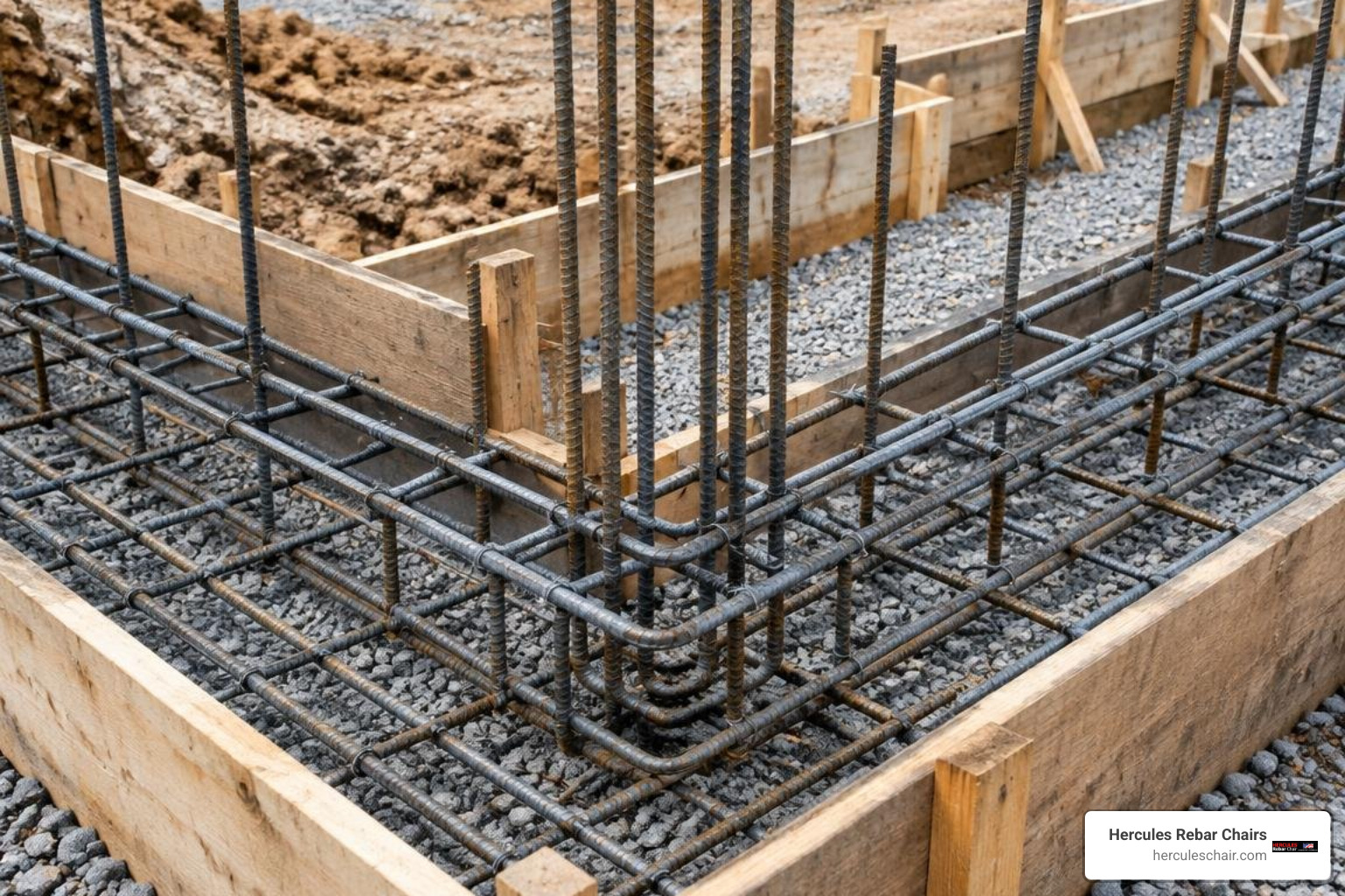
Straight rebar runs eventually end, requiring splices to preserve tensile continuity. Never butt bar ends together inside a footing trench. A lap splice must overlap by a code-specified length—typically 40 bar diameters or a minimum of 15 to 24 inches for standard #4 bars in normal-weight concrete—secured with 16-gauge tie wire.
Corners require careful detailing. Foundation fractures often develop at directional changes because stress concentrates at intersections. Rather than ending straight bars at a corner, bend bars into full 90-degree L-shapes with legs extending at least 24 inches past the turn, or install dedicated corner bar ties. Implementing code-compliant rebar layouts for concrete footings ensures stress transfers smoothly through corners without cracking the concrete.
Tying Footings to Stem Walls: Dowels, Keyways, and Anchor Bolts
Connecting the footing to the stem wall prevents the wall from shearing off its base during lateral earth movement. Builders achieve this connection using vertical rebar dowels combined with a beveled 2×4 keyway pressed into the wet footing surface.
Vertical #4 dowels should be tied to the horizontal footing rebar using standard 6-inch 90-degree hooks, extending upward at least 14 to 24 inches into the stem wall at a maximum spacing of 4 feet on center. These vertical bars overlap with the stem wall horizontal steel and tie into anchor bolts embedded a minimum of 7 inches at the sill plate. You can reference step-by-step footing reinforcement details and layouts to confirm dowel alignment before pouring your footing.
Best Practices for Supporting and Placing Steel Reinforcement
The most common field mistake is setting rebar directly on subgrade dirt or propping it up on loose rocks and wood scraps. Reinforcing steel must be fully encapsulated in concrete to develop its rated tensile yield strength and resist subsurface corrosion.
Maintaining Code-Required Clearances with Dedicated Chairs
According to ACI 318 and IRC specifications, steel cast against and permanently exposed to earth requires a minimum of 3 inches of concrete cover on the bottom and sides. If rebar rests on dirt or sits within an inch of the trench edge, groundwater wicks into the steel, causing rust, internal expansion, and concrete spalling.
At Hercules Rebar Chairs, we manufacture high-strength, code-compliant supports designed for rough trench conditions. Our bright red footer stands support multiple bars at exact code elevations without sinking into loose soil. Using dedicated stands keeps your steel stable when concrete drops from a pump hose. For layout patterns, check our practical guide to rebar footing stands alongside our footer stand placement and spacing guide to support your rebar grid correctly every 4 to 5 feet.
Material Selection: Standard Steel, Epoxy-Coated, and Fiberglass Alternatives
Carbon steel remains the construction industry standard, but specific site conditions warrant alternative rebar materials to prevent corrosion and premature foundation failure.
| Reinforcement Material | Primary Advantages | Common Applications | Key Limitations |
|---|---|---|---|
| Standard Carbon Steel (ASTM A615) | High yield strength, ductile, cost-effective, easy to bend on-site | Standard residential spread footings and commercial slabs | Vulnerable to rust if concrete cover is compromised |
| Epoxy-Coated Steel (ASTM A775) | Barrier coating protects steel against corrosive chemicals | Coastal sites, high-water tables, and deicing salt exposure | Coating can chip during handling; requires plastic-coated tie wire |
| Glass Fiber Reinforced Polymer (GFRP) | 100% non-corrosive, lightweight, non-conductive | Highly acidic soils, marine retaining footings, MRI facilities | Cannot be bent in the field; lower shear capacity |
| Galvanized Rebar (ASTM A767) | Sacrificial zinc coating provides long-term rust resistance | Humid coastal environments and exposed structural elements | Higher material cost than standard black steel |
Pre-Pour Inspection Protocol and Field Error Prevention
Once concrete is poured, correcting misplaced or unseated rebar is difficult and costly. Establishing a thorough pre-pour verification routine prevents job-site delays, structural defects, and failed inspections.
Installing and Inspecting Rebar for Footing Projects Before the Pour
Before calling for a foundation inspection, verify your trench against the approved structural plans. Use this pre-pour checklist:
- Subgrade Verification: Ensure the footing rests on undisturbed natural earth or structural fill compacted in maximum 8-inch lifts. Remove loose soil, standing water, and organic debris.
- Clearance and Cover: Check that all bars have at least 3 inches of clearance from bottom soil and 1.5 to 2 inches from side forms.
- Bar Size and Spacing: Match bar sizes (#4, #5) and spacing dimensions directly to the approved plan schedule.
- Lap Splice Dimensions: Verify all longitudinal splices overlap by at least 15 to 24 inches and are tied tightly with 16-gauge steel wire.
- Electrical Grounding (UFER): Verify that the 20-foot bare copper conductor or continuous rebar electrode is securely connected for electrical service grounding per NEC guidelines.
Consulting an official residential footing inspection checklist alongside our guide on how to install rebar in footings the right way will help keep your site organized and inspection-ready.
Critical Mistakes That Cause Foundation Inspection Failures
Building inspectors frequently reject footing excavations due to avoidable layout and support errors. The most common violation is resting rebar on loose dirt clods, clay mounds, or scrap 2×4 blocks. Wood rots over time and creates direct paths for water intrusion, while dirt clods collapse under wet concrete and expose the steel.
Another common issue is mud-caked rebar. When excavators work in wet trenches, clay often coats the steel, preventing concrete from bonding with the rebar’s deformations. If soil caves in, clean the bars thoroughly before placing concrete. Reviewing these fundamentals for mastering rebar placement for durable foundations will help your crew avoid expensive re-inspections.
Frequently Asked Questions About Footing Reinforcement
Is rebar required in footings for low-risk seismic categories (SDC A–C)?
Under the prescriptive provisions of the IRC, plain concrete footings without rebar are permitted in Seismic Design Categories A through C, provided the soil has adequate bearing capacity and the structure fits standard height and load limits. However, local amendments, geotechnical reports, or building designers often require at least one or two continuous #4 bars for crack control and added safety against settlement.
What is the minimum lap splice length for #4 rebar in footings?
For standard #4 deformed steel bars in residential concrete footings, the standard lap splice length ranges from 15 to 24 inches (or roughly 30 to 40 bar diameters). Always check your approved structural drawings, as local codes and engineered plans may specify longer splices in high seismic zones or weaker concrete mixes.
Can I substitute #3 rebar for #4 rebar in residential footings?
No. You should never downsize specified rebar without written approval from your structural engineer or local building official. A #4 bar provides a cross-sectional area of 0.20 square inches, whereas a #3 bar offers only 0.11 square inches—nearly a 45% reduction in tensile capacity. Downsizing steel reduces load capacity and will result in a failed pre-pour inspection under modern IRC and CRC codes.
Conclusion
A durable building depends on a stable foundation. While unreinforced concrete can carry heavy downward weight, it relies on steel reinforcement to resist soil movement, frost heave, and seismic tension. Sizing your bars properly, overlapping splices securely, and supporting steel with dedicated chairs ensures your footings meet code and provide lasting structural support.
At Hercules Rebar Chairs, we have supplied over 14 million USA-made red rebar chairs to help builders maintain exact concrete clearances and pass pre-pour inspections. For detailed spacing charts and layout techniques on your next project, explore our ultimate guide to spacing and supporting footing rebar.