

Why Reinforcement Steel for Concrete Matters
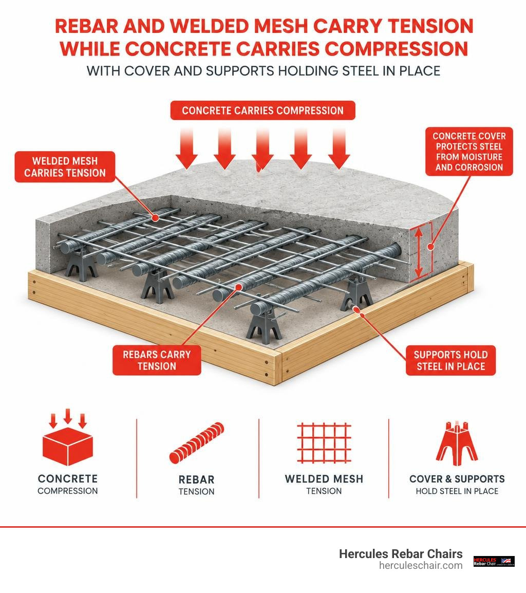
Reinforcement steel for concrete helps concrete carry loads that would otherwise pull it apart. Concrete is strong under compression but weak under tension. Steel bars and welded wire mesh add tensile strength, while the concrete around them transfers loads and protects the steel.
For a reliable pour, choose the bar or mesh grade shown on the plans, then check its spacing, concrete cover, and support before placing concrete. Those details help the steel do its job and reduce the risk of cracks and corrosion.
I’m Jordan Harris, a Tennessee-licensed structural engineer who spent five years working on large concrete and steel projects. Today, I help develop rebar supports at Hercules Rebar Chairs, drawing on that experience with reinforcement steel for concrete to make placement more dependable.
Types and Classifications of Reinforcement Steel for Concrete

Reinforcing steel comes in several configurations, primarily categorized by profile geometry, manufacturing method, and chemical composition. Choosing between bar schedules and mesh layouts requires evaluating structural demands, handling needs, and how the steel integrates into your forms. Selecting the right options begins with exploring essential concrete reinforcement products.
Steel reinforcement falls into three main product categories:
- Deformed Reinforcing Bars: Hot-rolled or cold-worked steel with surface protrusions (ribs) that mechanically interlock with the surrounding concrete matrix.
- Plain Round Bars: Smooth circular steel bars used primarily for dowels at expansion joints or specialized structural ties where sliding bond behavior is intentionally required.
- Welded Wire Reinforcement (WWR): A grid of longitudinal and transverse cold-drawn or cold-rolled wires resistance-welded at every intersection.
Deformed Bars, Welded Wire Mesh, and Fabric Geometries
The surface geometry of deformed steel dictates how effectively stresses transfer between the steel and concrete. Deformations consist of transverse ribs spaced along the bar and longitudinal ribs running parallel to the axis.
Engineers quantify this mechanical interlock using the relative projected rib area ($fR$). For deformed bars with diameters between 10.0 mm and 50.0 mm, international standards mandate a minimum $fR$ of 0.056. This ensures the bar bites into the concrete matrix before significant slip occurs.
Welded wire reinforcement relies on both surface deformations and the rigid resistance of welded intersections. According to manufacturing standards, the shear strength of welded joints must resist a direct shear force of at least:
$$\text{Shear Strength} \ge 0.5 \times fy \times As$$
Where:
- $f_y$ is the specified yield strength of the steel grade.
- $A_s$ is the nominal cross-sectional area of the largest bar at the welded joint.
A standard rectangular welded wire fabric style, such as 6×6 – W2.9 x W2.9, features a nominal weight of 42 lb/100 ft². Compare that to heavier styles like 6×6 – W4.0 x W4.0 at 58 lb/100 ft². Understanding these dimensional profiles is easier when reviewing welded wire mesh specifications.
Mechanical Properties and Grades of Reinforcement Steel for Concrete
Reinforcing steel grades reflect their yield point, ultimate tensile strength, ductility, and chemistry. Under standards such as the AS/NZS 4671:2019 steel reinforcement specifications, reinforcement is designated by profile, yield strength, and ductility class (e.g., D500N16 designates a Deformed bar, 500 MPa yield, Normal ductility, 16 mm diameter).
Weldability is dictated by the Carbon Equivalent Value (CEV). For standard grades ($\le 500\text{ MPa}$), chemistry limits prevent heat-affected zone brittleness:
- Maximum CEV (Cast Analysis): 0.49
- Maximum CEV (Product Analysis): 0.51
$$CEV = C + \frac{Mn}{6} + \frac{Cr + Mo + V}{5} + \frac{Ni + Cu}{15}$$
You can check your project’s specific requirements in our guide to rebar sizes and grades.
| Grade & Ductility Designation | Minimum Lower Characteristic Yield ($R_{ek.L}$) | Maximum Upper Characteristic Yield ($R_{ek.U}$) | Tensile-to-Yield Ratio ($Rm / Re$) | Minimum Uniform Elongation ($A_{gt.k.L}$) | Primary Application Field |
|---|---|---|---|---|---|
| 250N (Plain/Deformed) | 250 MPa | 325 MPa | $\ge 1.08$ | $\ge 5.0\%$ | Light civil, slabs, dowels |
| 300E (Seismic) | 300 MPa | 380 MPa | $1.15 \le \text{ratio} \le 1.50$ | $\ge 15.0\%$ | Seismic detailing, low-rise |
| 500L (Low Ductility) | 500 MPa | 650 MPa | $\ge 1.03$ | $\ge 1.5\%$ | Prefabricated mesh, driveways |
| 500N (Normal Ductility) | 500 MPa | 650 MPa | $\ge 1.08$ | $\ge 5.0\%$ | Standard commercial building frames |
| 500E (Earthquake/Seismic) | 500 MPa | 600 MPa | $1.15 \le \text{ratio} \le 1.40$ | $\ge 10.0\%$ (Deformed) | Seismic moment frames, bridges |
| 600N / 750N (High Strength) | 600 / 750 MPa | 780 / 975 MPa | $\ge 1.08$ | $\ge 5.0\%$ | High-rise columns, congestion relief |
Detailing Rules, Spacing Limits, and Minimum Reinforcement
Concrete cracking is inevitable because of drying shrinkage, temperature swings, and flexural loading. Proper reinforcement detailing controls crack widths and prevents sudden, brittle failures. When steel yields before concrete crushes, members deflect noticeably, giving occupants clear warning before structural collapse.
Designers must calculate the minimum area of steel ($A_{s,\min}$) for tension zones to exceed the concrete section’s cracking moment ($M_{cr}$):
$$A_{s,\min} = 0.26 \frac{f_{ctm}}{f_{yk}} bt d \quad (\ge 0.0013\, bt d)$$
Where:
- $f_{ctm}$ is the mean tensile strength of the concrete.
- $f_{yk}$ is the characteristic yield strength of the steel.
- $b_t$ is the mean width of the tension zone.
- $d$ is the effective depth to the reinforcement centroid.
Practical guidelines for international structural detailing can be reviewed in the reference work on detailing of reinforcement for building members.

Fabrication and cutting errors quickly compromise structural performance on-site. Verifying cross-sectional callouts is straightforward using accurate bar measurement and sizing.
Anchorage Lengths, Mandrel Bends, and Clear Spacing Limits
Reinforcement transfers stress to concrete via bond over a specific development length ($ld$). If a bar isn’t anchored properly, it will pull free before reaching its yield strength ($fy$).
To prevent internal concrete crushing during bar fabrication, bends and hooks must wrap around standard mandrels of minimum diameter ($d_{br}$):
- For Bar Diameters $\le 16\text{ mm}$: Minimum mandrel diameter = $4\phi$
- For Bar Diameters $> 16\text{ mm}$: Minimum mandrel diameter = $7\phi$
- For Welded Wire Fabric & Stirrups: Minimum mandrel diameter = $4\phi$
Clear spacing between parallel bars must allow coarse aggregate to pass without honeycombing:
$$\text{Clear Spacing} \ge \max\left(k1 \cdot \phi,\; dg + k_2\text{ mm},\; 20\text{ mm}\right)$$
Where $\phi$ is the nominal bar diameter, and $d_g$ is the maximum aggregate size (typically adding 5 mm to aggregate size).
The clear distance between parallel bars must measure at least 1.5 times the nominal bar diameter, 1.5 times the maximum coarse aggregate size, or 1½ inches (38 mm), whichever is greatest. Full placement and detailing standards are compiled within the ACI 315R-18 reinforcement detailing guide.
Splicing, Lapping, and Mechanical Connections
Bars cannot run infinitely through long pours. Joining continuous runs requires lap splices, welds, or mechanical couplers.
Lap splices rely on load transferring through the concrete between adjacent bars. Key detailing rules include:
- Lap lengths ($l0$) must account for concrete strength, bar size, cover, and local splitting forces: $$l0 = \alpha1 \alpha2 \alpha3 \alpha5 \alpha6 \, l{b,\text{rqd}}$$
- Bars at lap splices should not sit farther apart than one-fifth of the lap length or 6 inches (150 mm).
- Lap splices should be staggered away from high-stress zones. Avoid lapping more than 50% of the tensile steel at any single section.
In heavily congested members like bridge bents and high-rise columns, overlapping large bars (#11, #14, or #18) causes severe aggregate blockage. In these tight conditions, contractors transition to rebar couplers for mechanical connections to create continuous load paths without adding bulk.
Ductility Classes and Seismic Performance
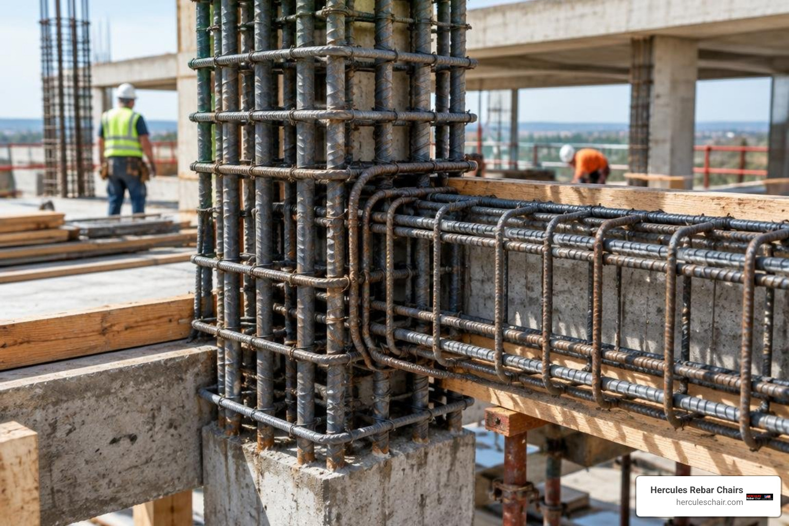
During an earthquake, structures absorb seismic energy through controlled, inelastic deformation—a property known as ductility. Without ductile steel, cyclic loading snaps reinforced concrete members abruptly.
Ductility classes define a steel’s plastic deformation capacity:
- Class L (Low Ductility, $A_{gt} \ge 1.5\%$): Restricted to driveways, precast floor planks, and non-structural slabs where seismic ductility is not required.
- Class N (Normal Ductility, $A_{gt} \ge 5.0\%$): Standard grade for static, wind-dominant, and moderate gravity frames.
- Class E (Earthquake/Seismic, $A_{gt} \ge 10.0\%$ to $12.0\%$): Mandatory for seismic force-resisting systems (SFRS), moment-resisting frames, and shear wall boundary elements.
Earthquake design relies on specific capacity design principles. Steel must not exceed its specified upper yield strength limit ($R_{ek.U} \le 600\text{ MPa}$ for Grade 500E). If the steel is unintentionally over-strength, plastic hinges will not form where intended, causing sudden shear failure elsewhere in the concrete member. Detailed strategies for long-term structural integrity can be found in our overview of strategies for durable reinforced concrete.
Best Practices for Placing and Protecting Reinforcement
Steel left sitting on subgrade or pressed against wooden formwork will corrode rapidly once exposed to moisture and air. Concrete cover shields steel from environmental carbonation and chloride attack, while also insulating it during a fire.
Review critical concrete cover guidelines across standard project conditions:
- Cast against and permanently exposed to earth: 3.0 in (75 mm)
- Formed surfaces exposed to weather/soil (#6 through #18 bars): 2.0 in (50 mm)
- Formed surfaces exposed to weather/soil (#5 bar and smaller): 1.5 in (40 mm)
- Beams and columns (ties, stirrups, spirals): 1.5 in (40 mm)
- Slabs and joists (not exposed to weather/ground): 0.75 in (20 mm)
- Corrosive highway bridge decks (AASHTO standard): 2.5 in (65 mm)
Before concrete placement, verify the essentials covered in our guide to rebar support essentials.
Placement and Support of Reinforcement Steel for Concrete
To ensure your steel stays securely in place during heavy concrete placement and vibration, follow these critical inspection steps:
- Subgrade Preparation: Check that the subbase is fully compacted and level. Skids or pallets should keep raw steel clean and elevated prior to field assembly.
- Chair Selection: Choose chairs sized to provide exact specified cover. Hercules Rebar Chairs feature wide, stable bases designed to prevent punching through vapor barriers or sinking into compacted subgrade.
- Spacing Intervals: Place chairs along grids spaced between 2.0 ft and 3.5 ft (0.6 m to 1.1 m) in both directions. This keeps workers from deflecting the steel mat when walking on it during pours.
- Tie Wire Security: Fasten intersections securely with 16-gauge annealed tie wire. Snap-ties, saddle ties, or figure-eight ties prevent shifting under concrete pump discharge.
- Clearances and Cleanliness: Inspect the formwork for debris, tie-wire clippings, pooled water, and oil. Unprotected metal chairs must maintain at least 0.75 in (20 mm) concrete cover; plastic and plastic-coated chairs require at least 0.5 in (13 mm).
To choose the right supports for your project, consult our comprehensive rebar chair selection guide.
Quality Control, Testing, and Product Conformity
Site compliance relies on rigorous quality assurance protocols that verify mill test reports against independent laboratory benchmarks:
- Long-Term Quality (LTQ) vs. Batch Testing: LTQ tracks ongoing manufacturing data over hundreds of production runs to confirm characteristic values statistically ($p = 0.90$ with a $90\%$ confidence limit), while standard batch testing only confirms the physical properties of a single 50-tonne heat.
- Mass Per Metre Length Tolerances: For any size reinforcing bar, the measured mass tolerance must remain within $\pm 4.5\%$ of the theoretical nominal mass.
- Welded Wire Mesh Integrity: If broken welds exceed 1% of the total welded intersections across a single sheet, the material is subject to rejection.
- Laboratory Accreditation: Physical verification tests must be conducted by laboratories accredited to ISO/IEC 17025 using standardized tensile testing protocols.
Frequently Asked Questions About Concrete Reinforcement Steel
What is the difference between Grade 500N and Grade 500E reinforcement steel?
Grade 500N is standard 500 MPa yield reinforcement with normal ductility ($A_{gt} \ge 5.0\%$), engineered for general building applications dominated by static loads.
Grade 500E is specialized seismic steel with higher uniform elongation ($A_{gt} \ge 10.0\%$ for deformed bars). It also features tight upper-yield limits ($R_{ek.U} \le 600\text{ MPa}$) to ensure plastic hinges form predictably without overstressing adjacent connections.
How does relative rib area affect the bond between rebar and concrete?
The relative rib area ($f_R$) measures the ratio of the projected area of all transverse ribs to the bar’s overall cylindrical surface area.
A minimum $f_R$ of 0.056 (for bars 10 mm to 50 mm in diameter) ensures the steel mechanically engages the cured concrete paste. This prevents slip, controls crack widths, and shortens development lengths.
What are the standard lap splice requirements for reinforcing bars?
Standard lap splices generally range from 30 to 60 bar diameters ($30\phi\text{ to }60\phi$), depending on concrete strength, bar size, position (top vs. bottom bars), and local stress conditions.
Lap lengths are calculated per ACI 318 or Eurocode 2 provisions. Adjacent parallel bars in a lap splice should not be positioned farther apart than one-fifth of the lap length or a maximum of 6 inches (150 mm).
Conclusion
Reinforced concrete performance relies on two key factors: selecting the correct steel grade and placing it accurately in the forms. Missing design cover by even half an inch can cut a member’s flexural capacity by 15% and accelerate long-term corrosion.
Every detail matters on the job site—from checking heat chemistries and monitoring relative rib areas to tying tight splices and placing dependable rebar supports.
At Hercules Rebar Chairs, our signature red supports provide dependable support across jobs of all sizes. Over 14 million chairs sold help crews nationwide keep steel tied off and positioned securely, preventing structural delays and ensuring code compliance.
Plan your next pour with our practical concrete slab thickness and reinforcement guidelines to ensure clean, durable concrete placement.