

How Rebar Chair Testing Protects Concrete Cover
Rebar chair testing checks whether a support can hold reinforcement at the right height under construction loads. Review its rated load and height, check how much it bends under load and whether it recovers, then test the planned chair spacing on the jobsite with expected worker and equipment loads. Inspect the reinforcement before the pour. After placement, a cover-depth scan can show whether the steel stayed in position.
Product tests such as those in AS/NZS 2425:2015 assess chair performance. ACI 117 addresses placement tolerances for the reinforcement, not a load rating for the chair. Both matter: a strong chair at the wrong height can still leave the wrong cover.
I’m Jordan Harris, a Tennessee-licensed structural engineer with experience on large concrete projects and in rebar support manufacturing. I’ll use that background to explain rebar chair testing from product checks through post-pour verification.
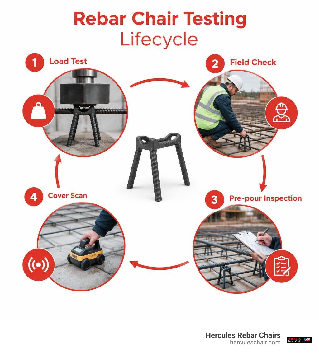
Simple rebar chair testing word guide:
Core Standards and Protocols in Rebar Chair Testing
Reinforced concrete depends on steel reinforcement staying exactly where design drawings place it. When workers step across reinforcing mats, or when fresh concrete drops from pump lines, support accessories absorb intense downward and lateral stresses. Standardized protocols exist to quantify exactly how much stress a support can handle before yielding or deflecting past allowable tolerances.
The gold standard for physical product evaluation is outlined in AS/NZS 2425:2015 bar chair standards. This standard sets strict parameters for minimum load capacity, permanent plastic deflection, dimensional accuracy, structural stability, and batch traceability. Under these guidelines, supports undergo rigorous mechanical evaluations so that under heavy construction activity, the reinforcement does not settle toward the bottom formwork or subgrade.
Dimensional tolerances are equally strict. A chair must be manufactured to within fractions of an inch of its designated nominal height. If a unit deviates by even a tiny margin at the factory gate, it introduces systematic elevation errors across thousands of square feet of concrete. Traceability protocols ensure that production runs carry clear supplier and batch identification markings, allowing testing laboratories and field inspectors to verify that on-site units match certified lab test data.
Laboratory Load Capacity and Deflection Testing
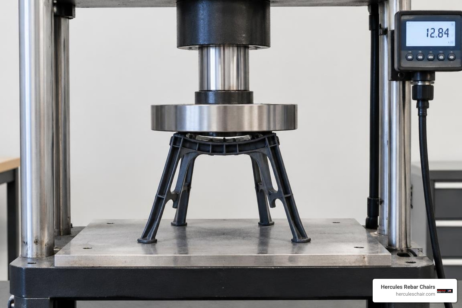
In controlled laboratory environments, technicians use calibrated universal testing machines and hydraulic presses to apply continuous vertical point loads to the cradles of rebar chairs. The primary objective is to evaluate both elastic deformation under working loads and permanent deflection once the load is removed.
A typical mechanical testing sequence involves:
- Setting the chair on a rigid, flat steel platen representing rigid formwork.
- Placing a steel mandrel matching standard rebar profiles (such as #4, #5, or #8 bars) into the cradle.
- Applying a specified test load steadily to simulate the static dead weight of heavy steel reinforcement and the dynamic surcharge of construction personnel.
- Measuring instantaneous deflection under full load.
- Releasing the load to determine the residual plastic deformation.
To achieve robust rebar chair code compliance, the chair must exhibit minimal permanent deflection. If a support deforms permanently under a worker’s footprint, the rebar mat remains sunken even after the worker walks away. Laboratory protocols also incorporate environmental aging and cold-temperature impact tests. In freezing weather, inferior plastic resins become brittle and shatter under shock loading, while in intense summer heat, lower-grade polymers can soften and sag under continuous rebar weight.
Field Verification and Rebar Chair Testing on the Jobsite
While factory certification establishes baseline strength, jobsite field testing verifies how the entire support assembly interacts with actual site conditions. Slabs poured over soft ground, granular bases, or vapor barriers behave very differently than reinforcement placed on rigid plywood formwork.
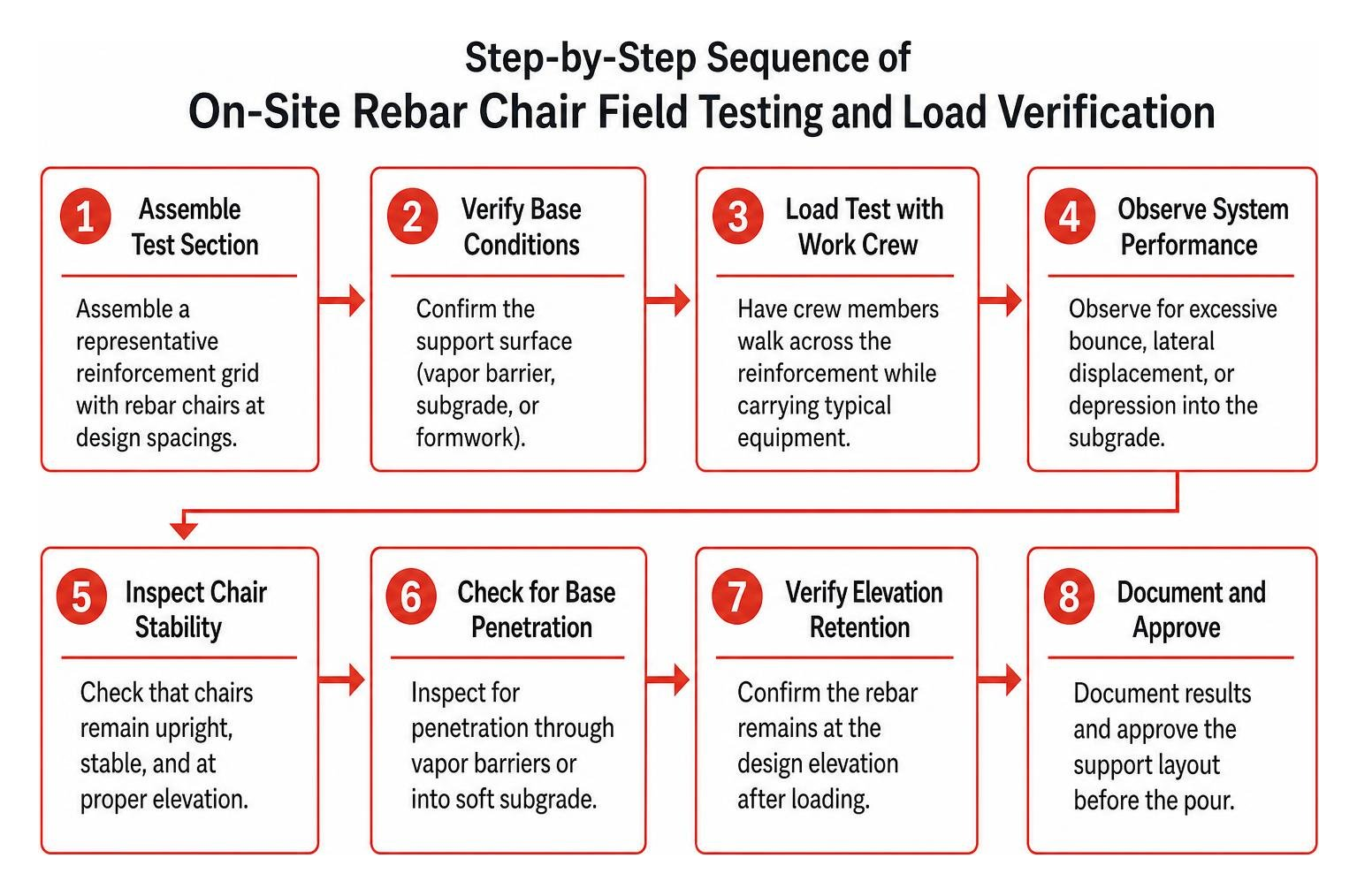
Following WRI guidelines for welded wire reinforcement supports, structural engineers and contractors conduct pre-pour mock-ups to validate support grids. By assembling a representative test section of the reinforcement grid and having crew members walk across it while carrying equipment, field personnel can observe whether the mats bounce excessively, displace laterally, or depress into the subgrade.
When inspecting rebar chairs properly, field inspectors check for base penetration. On slabs-on-grade, chairs with narrow legs can punch right through 10-mil or 15-mil polyethylene vapor retarders, creating punctures that allow ground moisture to seep into finished slabs. Chairs designed with broad, stable base plates or sand pads distribute point loads across a wide footprint, keeping vapor barriers intact and holding the rebar at design elevation.
Material Performance and Structural Failure Modes
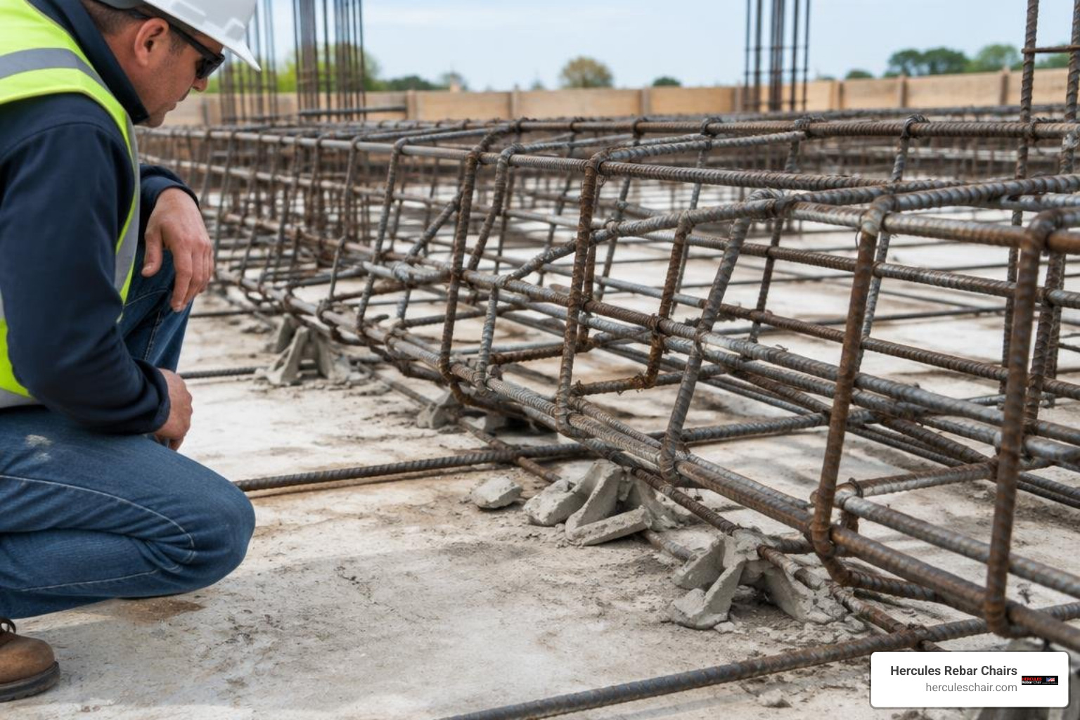
When rebar supports fail during a pour, the structural consequences are hidden deep inside the hardened concrete. Rebar chairs face severe multi-directional forces on the jobsite: the static weight of interconnected steel mats, dynamic foot traffic, concrete hoses being dragged across cages, and the impact force of wet concrete discharging from pump lines.
Common failure mechanisms include:
- Mechanical Crushing: Low-grade plastic or unreinforced supports collapse under heavy point loads.
- Tipping and Rolling: Chairs with narrow footprints tip sideways when rebar cages experience horizontal thrust from pump discharge.
- Cage Sag: Support chairs spaced too far apart allow flexible rebar or welded wire reinforcement to sag between support points.
- Vibration Displacement: High-frequency concrete consolidators (pencil vibrators) make unclipped chairs slide out of position along smooth formwork.
- Subgrade Settlement: Unpadded chair legs sink into sand beds or crush soft sub-slab rigid foam insulation boards.
Mechanical Crushing, Tipping, and Structural Collapse Risks
The structural risks associated with deficient rebar support are severe. A well-known historical example of reinforcement elevation failure occurred in the 1981 collapse of the Harbor Cay Condominiums in Florida. Forensic investigations revealed that chair spacers measuring only 4 inches high were installed in thin flat-plate slabs where taller chairs were required. This error drastically reduced the slab’s effective structural depth, contributing directly to a catastrophic punching shear failure at the columns during construction.
When top-mat negative moment steel settles even a fraction of an inch, the internal moment arm that resists bending tension shrinks dramatically. Understanding why concrete slabs require dedicated chair supports highlights the importance of mechanical stability: a support must possess the lateral stiffness and wide-stance geometry necessary to prevent rolling when workers step on cantilevered bars or when high-pressure pump lines strike the cage.
Material Evaluation: Rebar Chairs and Concrete Supports
Engineers select support materials based on load capacity, environmental exposure, and subbase type. The primary categories are high-strength engineered plastic chairs, precast concrete support blocks (dobies), and fabricated steel wire supports.
| Feature / Metric | Engineered Plastic Chairs | Precast Concrete Dobies | Steel Wire Chairs |
|---|---|---|---|
| Compressive Capacity | High (500–1,000+ lbs point load) | Extremely High (4,000–5,000+ psi) | High (wire gauge dependent) |
| Corrosion Resistance | 100% Non-Corrosive (Zero Rust) | 100% Compatible with Matrix | High Risk if Uncoated; Plastic-Tipped Available |
| Base Stability | Wide Base / Anti-Puncture Plate | Heavy, Flat Rectangular Base | Four-Leg Stance (Requires Sand Plates on Dirt) |
| Ideal Applications | Slabs-on-grade, suspended decks, precast | Deep footings, heavy mat foundations, civil work | Suspended structural slabs, bridge decks (coated) |
| Thermal Expansion | Engineered to match concrete limits | Identical to poured concrete | Matches structural rebar |
Reviewing our guide to rebar chair types and materials helps teams match specific job requirements with the proper support design. In corrosive environments or infrastructure projects governed by FHWA bridge deck inspection protocols, support accessories must prevent galvanic corrosion. For epoxy-coated or stainless rebar, chairs and tie wires must be fully non-metallic or heavily plastic-coated to avoid breaching protective coatings.
Building Code Compliance and Clear Cover Tolerances
Building codes treat reinforcement placement with high precision. The American Concrete Institute (ACI) and the International Building Code (IBC) mandate exact clear cover depths to shield carbon steel reinforcement from moisture, carbonation, chlorides, and fire.
ACI 318 Section 26.6.2 and ACI 301 establish strict requirements for concrete protection against environmental exposure. To review the legal framework governing these accessories, consult our guide on IBC code requirements for concrete supports. Under IBC Chapter 17, special inspections verify that reinforcing steel is placed, tied, and supported according to the approved construction documents. As detailed in professional field engineering rebar inspection practices, inspectors must confirm clearances before the general contractor receives written sign-off to place concrete.
Structural Impact of Cover Tolerances and Prohibited Materials
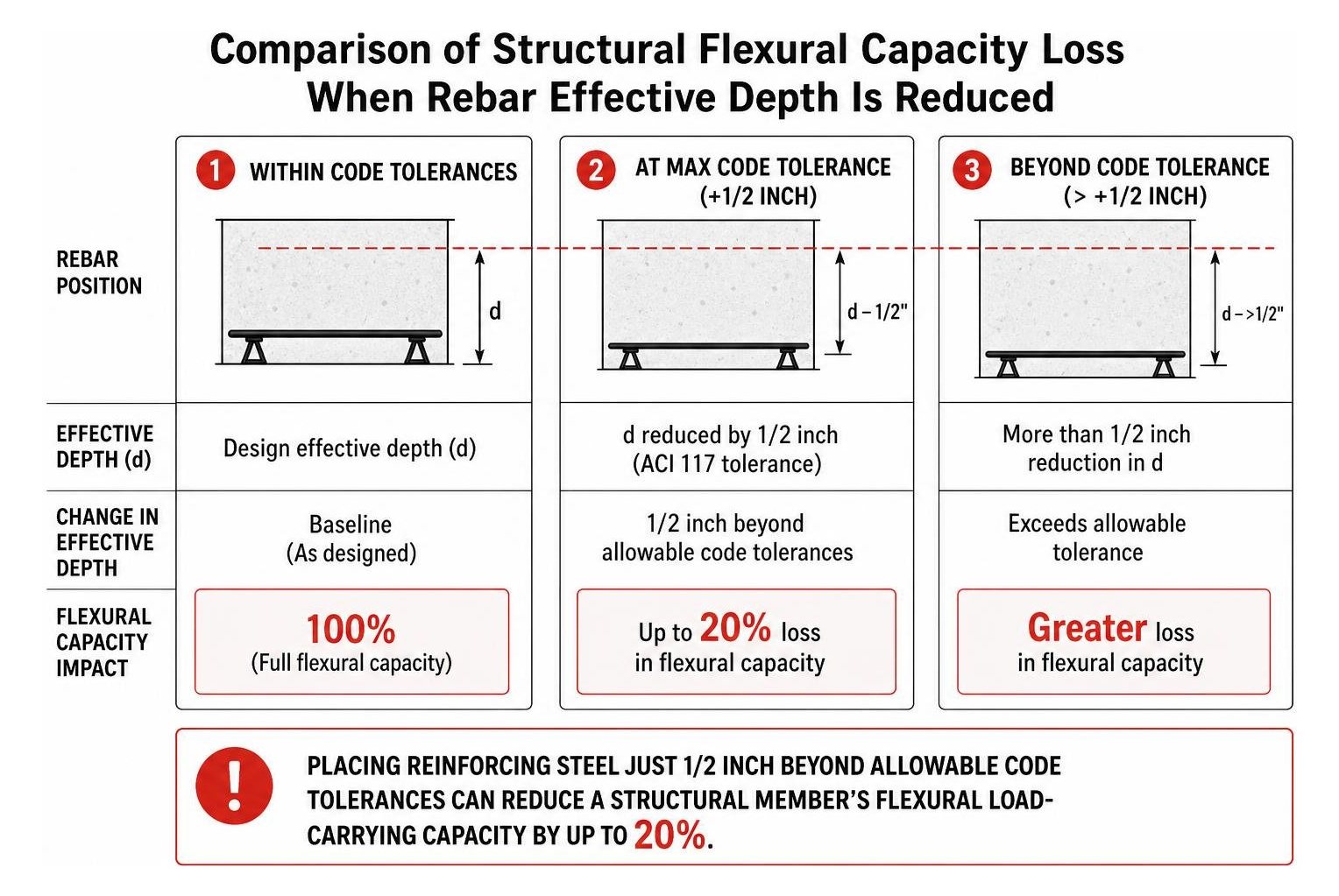
Tolerance standards are governed primarily by ACI 117 (Specification for Tolerances for Concrete Construction and Materials). For structural members with depths between 4 inches and 12 inches, ACI 117 establishes a clear concrete cover tolerance of 3/8 inch and an effective depth tolerance of 1/2 inch. For members deeper than 12 inches, the effective depth tolerance tightens to 3/8 inch.
These tight margins exist for structural safety: placing reinforcing steel just 1/2 inch beyond allowable code tolerances can reduce a structural member’s flexural load-carrying capacity by up to 20%.
Because precise clearance is vital, building codes and standard industry specifications explicitly prohibit makeshift support materials. The following items must never be used to support reinforcement:
- Clay Bricks: Highly porous, brittle, and prone to absorbing moisture and fracturing under freeze-thaw cycles.
- Wood Blocks: Organic material that absorbs water, rots over time, swells, and leaves voids and direct leak paths through the concrete.
- Rocks and Cobbles: Uncertified, irregular shapes that lack uniform dimensions and can introduce weak slip planes.
- Driven Bare Rebar Stakes: Driving steel pins into the earth creates a direct conduit for ground moisture to reach internal structural reinforcement, causing rapid galvanic corrosion, rust expansion, and catastrophic concrete spalling.
Certified supports must provide a compressive strength that matches or exceeds the surrounding concrete (typically 4,000 psi or higher for precast blocks) while preventing chemical contamination.
Grid Spacing and Load Distribution for Slabs and Decks
To prevent reinforcing mats from sagging between supports, chairs must be laid out in an engineered grid. Spacing is governed by bar diameter, wire gauge, and the anticipated construction traffic.
For welded wire reinforcement (WWR) in slabs-on-grade, industry standards recommend the following support spacing intervals:
- Light Wire (Smaller than W4 or D4, spaced under 12 inches): Space supports every 2 to 3 feet in both directions.
- Medium Wire (W4 to W8 or D4 to D8): Space supports every 3 to 4 feet.
- Heavy Structural Wire (W9 or D9 and larger, spaced 12 inches or greater): Space supports every 4 to 6 feet. Heavy wire styles allow workers to step between the grid wires directly onto the subgrade, drastically reducing direct dynamic loads on the supports.
On suspended slabs and elevated decks, top reinforcing mats must be supported by heavy-duty chairs spaced at intervals of 1.0 meter (approximately 3.3 feet) or less. In designated high-traffic work zones—such as pump hose transit corridors and screed runways—spacing should be tightened to 0.8 meters (approximately 2.6 feet) or less, as outlined in QA/QC Inspection and Test Plan guidelines for suspended slabs.
For advice on matching support spacing to slab geometry, explore our recommendations for choosing the right concrete rebar chair.
Post-Pour Quality Assurance: Non-Destructive Rebar Chair Testing
Once concrete is placed, visual inspection of rebar chairs is no longer possible. If chairs crushed, slipped, or tipped during the pour, the defect is buried within the hardened element. Modern quality assurance programs use non-destructive testing (NDT) to verify as-built concrete cover.
Following established non-destructive cover depth survey principles, field technicians use electromagnetic pulse-induction cover meters and ground-penetrating radar (ferro scanning) across cured slab surfaces. These instruments detect the precise location, orientation, and depth of embedded bars beneath the concrete surface without damaging the structure.
A post-pour cover survey evaluates:
- Mean Cover Depth: The statistical average cover across the structural element compared to design specifications.
- Minimum Cover Thresholds: Identifying localized thin spots where rebar floated upward or chairs settled downward.
- Bar Alignment and Grid Pitch: Verifying that bar spacing remained uniform during concrete consolidation.
When cover-depth surveys reveal deficient cover, the structure faces long-term durability risks. Insufficient cover allows the atmospheric carbonation front—where carbon dioxide neutralizes the protective alkaline pH of concrete—to reach the steel prematurely. In coastal environments or highway structures exposed to deicing salts, shallow cover allows chloride ions to penetrate and depassivate the protective oxide film on the steel, causing rust, expansion, and surface spalling.
Depending on survey findings, structural engineers may require remediation methods such as applying elastomeric surface sealers, installing carbon-fiber-reinforced polymer wraps, or applying bonded high-strength mortar overlays to restore required protective cover.
Frequently Asked Questions About Rebar Chair Testing
How do laboratory load tests verify that rebar chairs maintain cover depth under construction traffic?
Laboratory load testing applies static and dynamic point loads to rebar chairs using calibrated mechanical test rigs. Guided by standards such as AS/NZS 2425:2015, hydraulic rams apply representative working loads (simulating the weight of steel, wet concrete, and fully equipped workers) through steel mandrels resting in the chair cradle.
Technicians record instantaneous deflection and evaluate residual plastic deformation after unloading. If a chair deflects beyond allowable tolerances or suffers permanent structural failure, it is rejected. These tests confirm that the chair will maintain specified elevation under real-world jobsite conditions.
Why does placing rebar just 1/2 inch beyond tolerance reduce structural capacity by up to 20%?
Reinforced concrete operates as a composite structural system: concrete resists compressive forces in the top zone, while steel reinforcement carries tensile forces along the bottom. The structural capacity of any flexural member depends on its effective depth—the exact distance from the extreme compression fiber to the centroid of the tensile reinforcement.
When chairs are undersized or crush under load, the reinforcement rests closer to the neutral axis, shortening the internal moment arm. Because flexural capacity is directly proportional to this effective depth, losing just 1/2 inch of depth in a standard 5-inch or 6-inch slab reduces total bending resistance by up to 20%, leading to unexpected deflection, early cracking, or structural failure under service loads.
How should support materials be evaluated for compliance?
Support materials must be evaluated for compressive strength, moisture absorption, dimensional consistency, and chemical compatibility with the concrete matrix. Under ACI 301, supports must be manufactured from non-corrosive, non-absorbent materials.
Precast concrete blocks must have a certified compressive strength equal to or greater than the specified design concrete strength (typically 4,000 to 5,000 psi) and feature embedded tie wires for positive attachment. Engineered plastic supports must undergo structural load testing, environmental stress crack testing, and temperature stability testing to confirm they will not soften in high heat or turn brittle in freezing conditions. Makeshift supports like clay bricks, wood, or driven steel pins fail these criteria and are strictly prohibited by building codes.
Conclusion
Reinforced concrete structures are designed to last for generations, but their durability depends heavily on the small accessories that hold the internal steel skeleton in place. Rebar chair testing bridges the gap between theoretical structural calculations and the demanding physical reality of active construction sites. By combining factory load certification, pre-pour field mock-ups, strict spacing grids, and post-pour non-destructive cover surveys, engineers and contractors can be confident that structural steel will stay where it belongs.
At Hercules Rebar Chairs (a brand of the T.J. Harris Co.), we manufacture strong, reliable concrete supports engineered specifically for the concrete construction industry. Recognized as America’s #1 rebar chair with over 14 million units sold across the United States, our iconic red chairs are designed to save time and labor, ensure full building code compliance, and provide uncompromising load support on every pour.
To review slab design standards and reinforcement placement principles for your upcoming projects, explore our comprehensive guide on concrete slab thickness and reinforcement depth guidelines to ensure your concrete structures stand strong for their entire design life.