

Decode Rebar Shop Drawings Before Steel Reaches the Site
To read rebar shop drawings, start by matching the drawing revision to the current structural plans. Then trace each bar mark from the plan or section to the bar bending schedule (BBS). Confirm the bar size, spacing, shape, length, splice location, concrete cover, and support requirements before fabrication or placement begins.
These drawings turn an engineer’s design intent into instructions the fabricator and field crew can use. A clear set helps crews place steel in the right location, maintain cover, avoid clashes at openings and MEP penetrations, and keep congested areas buildable before concrete is poured.
The key is not to review every line in isolation. Read the general notes first, follow the bar marks through plans and sections, and use the BBS to verify what must be cut and bent. If a detail changes load paths, conflicts with another trade, or does not match the structural documents, pause and submit an RFI rather than making a field assumption.
I am Jordan Harris, a Tennessee PE with civil and structural engineering degrees and five years of experience on large concrete and steel projects. My work in engineering, manufacturing, and rebar support products gives me a practical view of how rebar shop drawings must work both on paper and during a real concrete pour.

Rebar shop drawings terms simplified:
Fundamental Detailing: Design Intent vs. Field Execution
In reinforced concrete construction, there is often a massive gap between what an engineer designs on a computer screen and what ironworkers tie in the mud. Structural contract drawings establish the overall strength, geometric constraints, and safety margins of a structure. However, a steel fabricator cannot cut or bend raw rebar solely from design blueprints, nor can rod busters assemble a cage without knowing exact dimensions and bundle tags.
This is why detailing exists. Shop drawings bridge design intent and physical assembly, translating general concepts into measurable, cuttable, and constructible elements. They establish drawing hierarchy, provide raw fabrication data, dictate installation sequencing, and ensure absolute dimensional accuracy across every square foot of the pour.
Structural Blueprints vs. Rebar Shop Drawings
Structural blueprints communicate structural parameters such as concrete compressive strength, nominal slab thicknesses, member dimensions, and primary steel area requirements. These drawings show where tension, compression, and shear forces travel, grounded in structural concrete principles. Yet, you will rarely see individual bar lengths, cut angles, or hook deductions called out piece by piece on a structural engineering sheet.

Rebar shop drawings, on the other hand, provide explicit fabrication and placement instructions. They assign unique bar marks to every piece, dictate precise lap lengths, detail hook orientations, and present step-by-step layouts for the ironworkers. To explore this distinction further, check out Rebar Shop Drawings: The Ultimate Guide for visual walk-throughs of structural transitions.
| Feature | Structural Engineering Drawings | Rebar Shop Drawings |
|---|---|---|
| Primary Purpose | Define design intent, loads, and member capacities | Provide step-by-step fabrication and field placement instructions |
| Prepared By | Licensed Structural Engineer (EOR) | Specialized Rebar Detailer or Steel Fabricator |
| Level of Detail | Typical section details, bar size/spacing notes | Individual bar marks, cut lengths, bend angles, exact lap points |
| Fabrication Utility | Cannot be used directly in the shop | Contains Bar Bending Schedules (BBS) for automated shearing/bending |
| Field Utility | Used for global coordination and building inspections | Used by ironworkers for unloading, staging, tying, and chairing |
Industry Compliance Standards: ACI, CRSI, and ASTM
To keep structures safe and compliant across the United States, shop drawings must strictly adhere to recognized industry standards. Detailing is not a creative writing exercise; every hook radius, lap length, and bend tolerance is governed by code.
- ACI 318 (Building Code Requirements for Structural Concrete): Mandates the structural engineering requirements, such as development lengths, seismic hooks, tension lap splices, and minimum concrete cover.
- ACI 315 (Guide to Presenting Reinforcing Steel Design Details): Standardizes how reinforcement details are drawn, marked, dimensioned, and scheduled for clarity across drafting disciplines.
- CRSI (Concrete Reinforcing Steel Institute) Manual of Standard Practice: Dictates standard fabrication practices, bending shapes, manufacturing tolerances, bundle tagging, and field placement guidelines.
- ASTM Specifications (e.g., A615, A706): Govern the metallurgical and mechanical properties of deformed carbon-steel and low-alloy weldable bars.
Following these specifications guarantees that steel delivered to the site matches the structural model and performs predictably over decades of service.
The Anatomy of Rebar Shop Drawings: Key Components and Symbols
When you unroll a complete set of shop drawings (or open an IFC model on a field tablet), you are looking at a multi-layered instructional system.
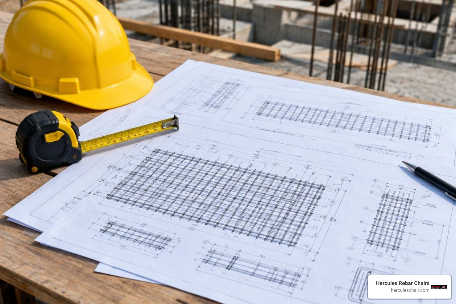
A professional rebar shop drawing package contains five foundational elements:
- Title Block & Revision History: Tracks project details, drawing release numbers, submission dates, and structural change orders.
- General Notes & Specifications: Lists concrete strengths, rebar grades (e.g., Grade 60 or Grade 80), clear cover requirements, lap tables, and chair spacing requirements.
- Plan Views: Top-down representations showing bar layout runs, spacing ranges, continuous steel, stagger patterns, and opening trim steel.
- Section Cuts and Elevations: Detailed cross-sections showing exact vertical elevations, hook orientations, clearance to formwork, and multilayer spacing.
- Callout Labels & Bar Marks: Encoded alphanumeric tags tied directly to the project’s bar bending schedule.
Decoding the Bar Bending Schedule (BBS) and Mark Numbers
The Bar Bending Schedule (BBS) serves as the project’s master bill of materials. It lists every piece of steel required for a specific structural element, broken down by shape, grade, dimension, and quantity.
A typical bar callout looks like this: 24 - 5A12 @ 12" T&B EW
- 24: Total count of pieces in that specific run.
- 5: Bar size (#5 bar, which is 5/8″ nominal diameter).
- A12: The unique Mark Number (often indicating shape configuration or member location).
- @ 12″: Center-to-center spacing.
- T&B: Placed in both the Top and Bottom mats.
- EW: Run Each Way (bidirectional grid).
Technical Detailing Workflows and Technology
Creating code-compliant rebar shop drawings requires a meticulous engineering workflow that aligns fabrication logistics with architectural and structural parameters.
Step-by-Step Detailing and Approval Workflow
- Information Gathering: The detailer collects the latest structural drawings, architectural layouts, MEP penetration plans, and project specifications.
- Drafting Layout & Geometry: Using specialized software, the detailer maps out the concrete boundaries, construction joints, pour sequences, and foundation layouts.
- Bar Placement & Splice Detailing: Reinforcement runs are placed within the geometric outline, adhering to ACI development lengths, hook configurations, and clearance standards.
- BBS Generation: The software compiles every individual piece into a comprehensive Bar Bending Schedule, summarizing bar tags, shapes, cut lengths, and total weights.
- Internal Quality Review: Senior detailers audit the package for dimensional continuity, constructability, and clash-free intersections.
- Submittal to Engineer of Record (EOR): The drawing set is submitted to the structural engineer for formal review and sign-off.
- Fabrication & Field Release: Once stamped “Approved as Noted” or “Approved,” drawings are sent to the fabrication mill for automated cutting and bundle tagging.
Modern Software and AI in Rebar Shop Drawings
Detailing has evolved from 2D manual drafting into highly intelligent 3D Building Information Modeling (BIM). Today, detailers rely on platforms like Tekla Structures, Autodesk Revit Structure, and AutoCAD to build reinforcement models at LOD (Level of Development) 350 to 400.
Modern 3D workflows allow automated clash detection between rebar, post-tensioning tendons, embed plates, anchor bolts, and plumbing sleeves before a single piece of steel is cut. Furthermore, emerging artificial intelligence tools and automated scripting algorithms can scan structural schedules, extract dimension data, and draft routine bar placements in minutes. These technological advances allow drafting teams to deliver turnaround times within 24 to 48 hours while cutting material waste by up to 12% across high-rise and infrastructure projects.
Engineering Review Checklist and Avoiding Site Mistakes
Reviewing rebar shop drawings is one of the most critical quality-control checkpoints in preconstruction. A simple drafting error on paper can quickly turn into days of costly field jackhammering or dangerous structural failures.
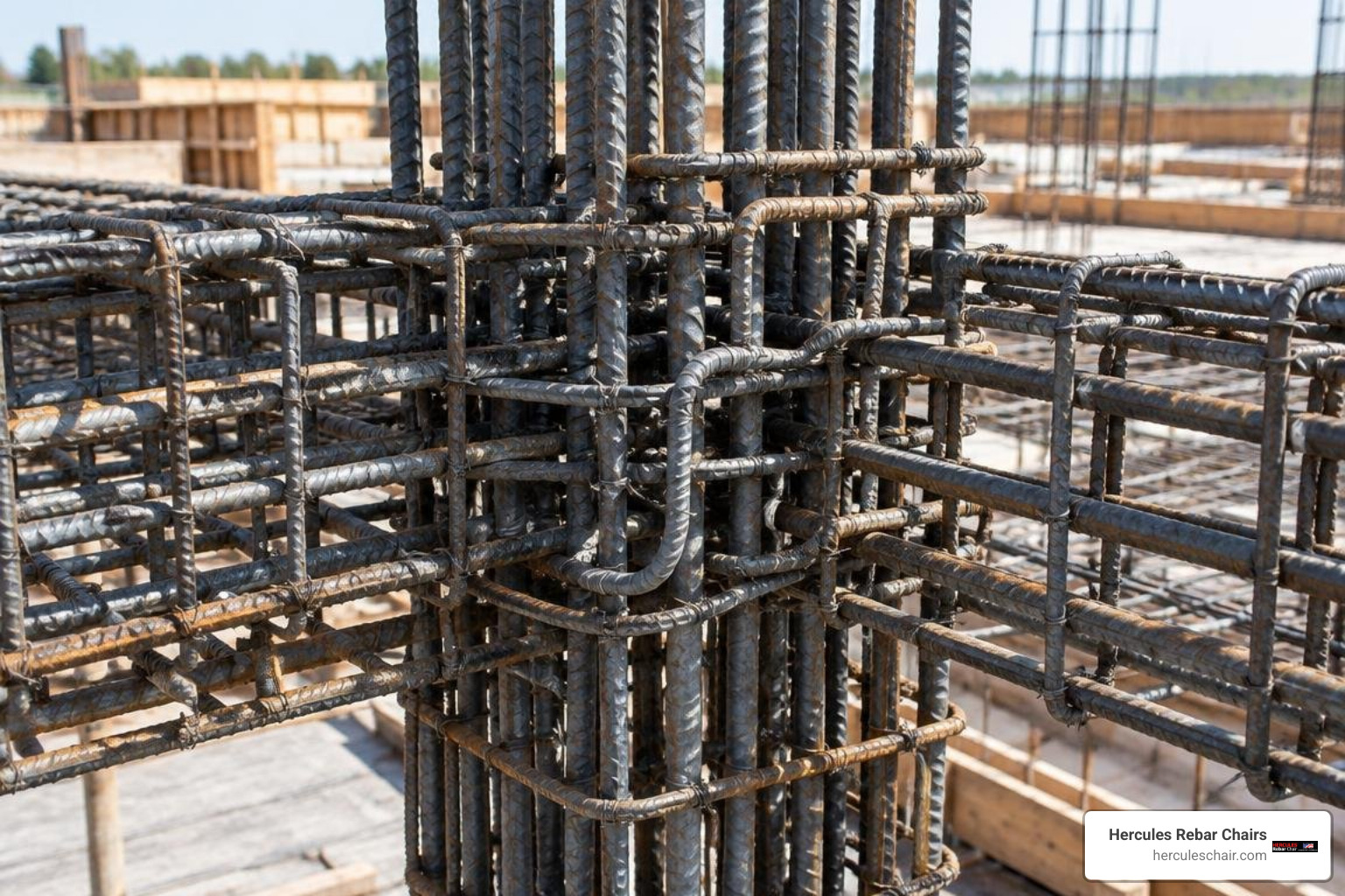
Common Detailing Errors and How to Prevent Them
- Overlooking Clear Cover Tolerances: Specifying standard bends without subtracting cover offsets leads to bars sticking out of forms.
- Congested Beam-Column Intersections: Placing top beam bars directly on the same elevation plane as column vertical offsets creates unbuildable “steel birdcages.”
- Inadequate Opening Reinforcement: Omitting diagonal trim bars around slab and wall penetrations leads to re-entrant corner cracking.
- Misaligned Lap Splices: Failing to stagger splices in high-stress zones violates seismic detailing provisions.
- Ignoring Pour Sequences: Detailing dowels that block formwork stripping or concrete chute access during multi-phase pours.
These errors can compromise everything from basic footing rebar placement to intricate slab reinforcement details.
A Structural Engineer’s Protocol for Shop Drawing Sign-Off
When structural engineers review shop drawing submittals, they must follow a structured, top-down review protocol:
- Global Information Check: Verify project names, sheet revisions, current addenda, and applicable code cycles. Confirm concrete strengths ($f’c$) and steel grades ($fy$).
- Typical Detail Comparison: Match shop drawing lap tables, hook standards, and corner details directly against structural typical details.
- Continuous Plan Review: Trace continuous top and bottom bars across spans. Ensure correct bar extensions past theoretical cutoff points.
- Section Cross-Check: Verify that section cuts accurately reflect clearance, layer spacing, and concrete covers for all environmental exposure classes.
- Bar Bending Schedule Spot-Check: Randomly spot-check 5% to 10% of BBS entries to verify cut lengths, standard hook deductions, and bar marks against plan callouts.
- Definitive Markup Clarity: Avoid vague notes like “Verify in Field.” Provide clear, actionable markups tied directly to contract sheet references.
Frequently Asked Questions About Reinforcement Detailing
What is the primary difference between structural drawings and shop drawings?
Structural drawings establish the design intent, member sizes, overall dimensions, concrete strengths, and required steel reinforcement areas. Rebar shop drawings translate that design intent into practical, fabrication-ready instructions. They provide individual bar marks, cut lengths, bending shapes, lap splice positions, clearance offsets, and detailed bar bending schedules that fabricators and field ironworkers need to build the structure.
How do bar bending schedules reduce construction waste on-site?
Bar Bending Schedules (BBS) consolidate exact bar counts, shapes, and cut lengths into optimized fabrication packages. Instead of cutting stock 20-foot or 60-foot bars randomly on-site—which creates massive scrap piles—fabricators use computer-controlled cutting machines to nest lengths efficiently. This process routinely reduces rebar material waste by up to 12% to 15%, saving thousands of dollars on commercial projects while reducing crane pick times.
Who is legally responsible for verifying rebar shop drawings?
The detailer is responsible for dimensional accuracy and transferring notes from the contract documents into the shop drawings. The general contractor must review and coordinate the drawings against all trades (including MEP and formwork) before submittal. Finally, the Structural Engineer of Record (EOR) reviews and approves the submittal to confirm compliance with design intent and applicable building codes before fabrication begins.
Master Your Rebar Detailing for Flawless Pours
Rebar shop drawings are the ultimate blueprint for structural resilience. When drafted with precision and read with an expert eye, they eliminate site clashes, protect project budgets, and guarantee that the steel inside the concrete performs as designed.
Once your shop drawings are approved and fabrication begins, ensure your site execution matches that engineering excellence. Elevating your steel with reliable bar supports protects your concrete cover from the first rebar tie to the final trowel finish.
Ready to level up your field installation? Check out our complete rebar placement guide and build with confidence from the ground up!