

Overview of Mechanical Coupler Systems and Code Classifications
To install a rebar coupler correctly, start by square-cutting the bar ends and preparing them for the coupler type. For threaded systems, cold-forge and roll the threads, then clean the bar ends and coupler threads. Align the bars coaxially, insert them fully into the coupler until they seat against the internal stop, and tighten with a calibrated torque wrench to the manufacturer’s specified torque. For shear-bolt couplers, insert both bars to the center stop and tighten the bolts in an alternating pattern until the heads shear off. Verify full thread engagement or bolt shear before concrete placement.
When reinforcing concrete, we often face structural elements where overlapping steel is either impractical or strictly prohibited by building codes. Traditional lap splices rely entirely on the surrounding concrete bond to transfer tensile and compressive forces. By contrast, a mechanical coupler creates a continuous, direct load path between two bars.
Under modern building codes such as ACI 318-19, mechanical splices are categorized into two primary classifications:
- Type 1 Mechanical Splices: Must develop at least 125% of the specified yield strength ($1.25 Ab fy$) of the reinforcing bar in both tension and compression. These are used in standard structural members outside regions of expected plastic yielding.
- Type 2 Mechanical Splices: Must satisfy all Type 1 strength requirements while also developing the full specified tensile strength ($f_u$) of the spliced bar. Because Type 2 splices ensure that failure occurs in the rebar rather than the connection, they are mandated in seismic yielding regions, such as the plastic hinge zones of special moment frames and structural shear walls.
In high-seismic zones, engineers must also account for stress concentration. ACI 318 mandates that mechanical splices in special structural systems be staggered—typically by at least 30 inches (750 mm)—between adjacent bars. This prevents a continuous weak plane across heavily loaded column or wall cross-sections. Finding compatible steel reinforcement couplers that match your structural drawings and seismic detailing requirements ensures smooth field assembly and uninterrupted code compliance.
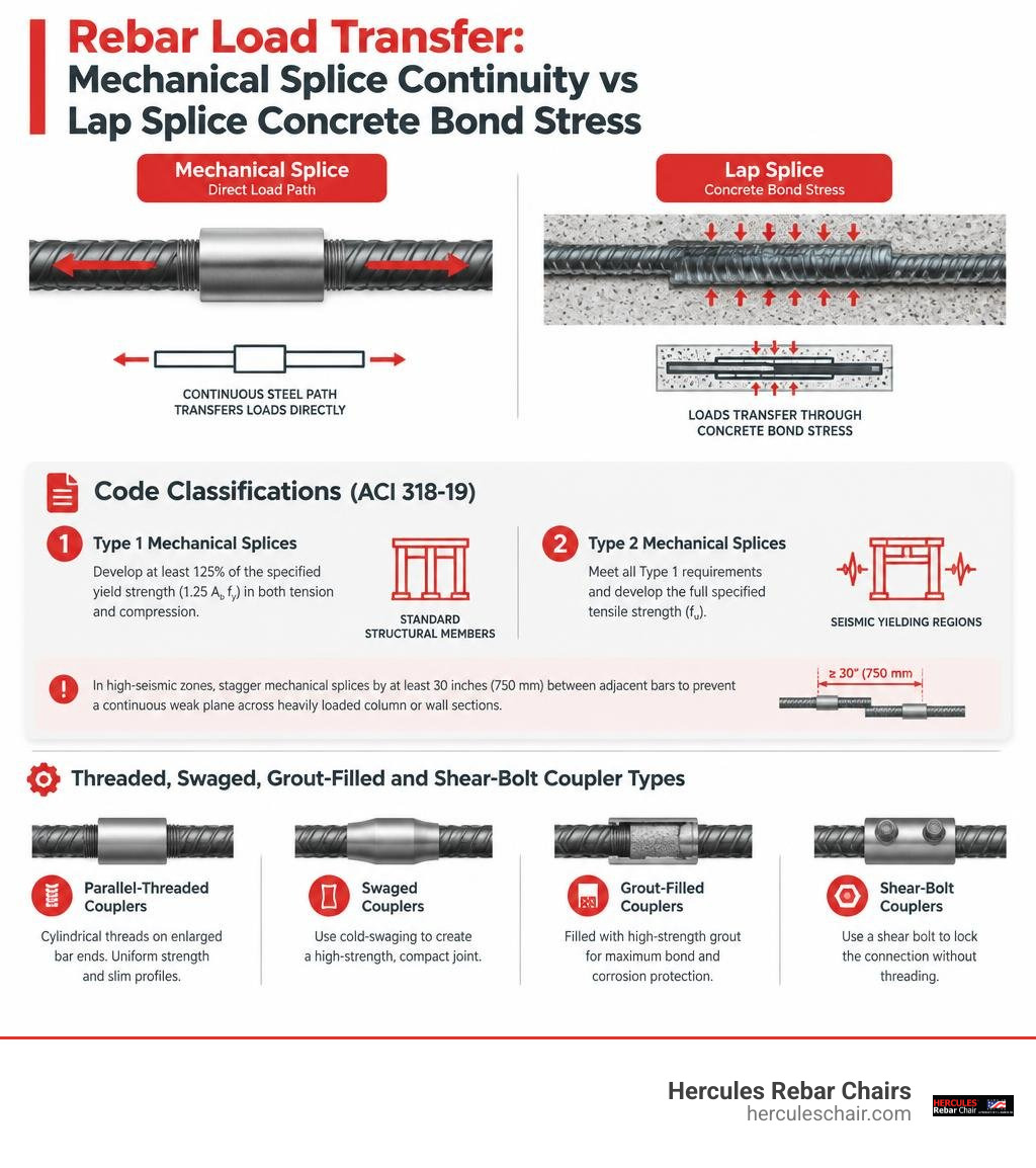
Threaded, Swaged, Grout-Filled, and Shear-Bolt Coupler Types
Selecting the correct coupler system depends on whether the steel bars can rotate, the availability of specialized tooling, and whether the project involves precast, cast-in-place, or retrofit work.
- Parallel-Threaded Couplers: Utilize cylindrical threads cut or rolled onto enlarged (cold-forged) bar ends. They offer uniform strength and slim profiles.
- Taper-Threaded Couplers: Feature tapered internal threads that eliminate cross-threading and allow rapid field tightening with fewer turns.
- Cold-Swaged Sleeves: Steel sleeves hydraulically pressed onto ribbed rebar, deforming the sleeve into the rebar deformations without requiring bar-end threading.
- Grout-Filled Sleeves: Wide cylindrical sleeves filled with proprietary high-strength non-shrink grout (often exceeding 100 MPa), widely used to connect precast columns and wall panels.
- Shear-Bolt (Lock-Screw) Couplers: Feature internal serrated grip rails and breaking bolts. They require no bar-end preparation and tighten until the bolt heads shear off at a calibrated torque.
| Coupler Type | Bar-End Preparation | Primary Installation Tooling | Primary Use Case / Application |
|---|---|---|---|
| Parallel-Threaded | Square cut, cold forging, thread rolling | Pipe wrench / Torque wrench | Standard new construction, high-rise columns |
| Taper-Threaded | Square cut, precision taper threading | Calibrated torque wrench | Fast-track cast-in-place framing, bridge decks |
| Cold-Swaged | None (clean sheared or cut bar ends) | Hydraulic swaging press | Retrofit work, non-weldable steel splicing |
| Grout-Filled | None (standard clean bar ends) | Grout pump / injection gun | Precast column-to-foundation and wall joints |
| Shear-Bolt | None (deburred, clean bar ends) | Pneumatic / electric impact wrench | Confined repairs, positional splices, retrofits |
Step-by-Step Rebar Coupler Installation Process
Proper preparation of the steel is the foundation of any mechanical splice. Skipping steps during fabrication or field assembly compromises the connection’s capacity.
Every threaded mechanical connection follows a clear fabrication sequence:
- Square Cutting: Saw-cut or cold-cut the bar ends perpendicular to the longitudinal axis. Avoid torch cutting, which creates uneven thermal stress and jagged edges.
- Cold Forging (Bar Upsetting): Upset the bar ends using a hydraulic forging machine to enlarge the core diameter. This ensures the root diameter of the cut thread retains a cross-sectional area equal to or greater than the original bar.
- Thread Rolling: Roll precision parallel or tapered threads onto the upset end to match coupler specifications.
- Quality Verification: Test prepared threads using go/no-go gauges.
- Thread Protection: Immediately seal the threads with plastic protective caps to prevent jobsite corrosion, concrete splatter, and mechanical damage before assembly.
Reviewing an established rebar mechanical splices and couplers field guide helps field crews maintain rigorous quality control throughout this fabrication phase.
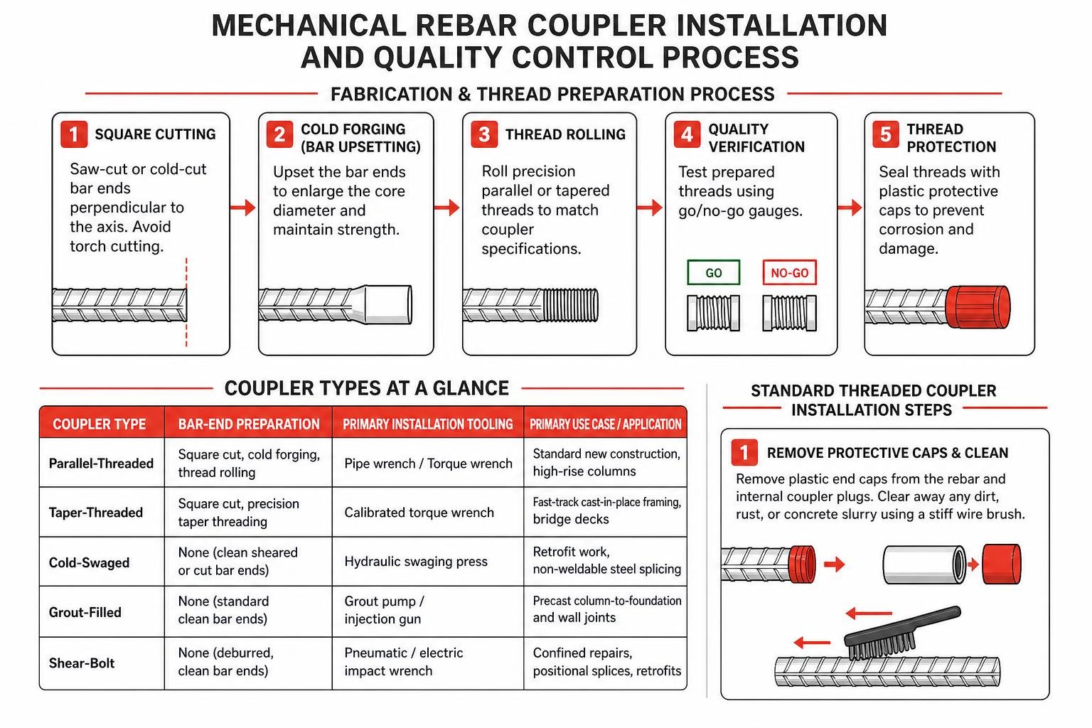
Standard Threaded Rebar Coupler Installation Steps
When working with standard threaded rebar couplers, both bars (or at least the incoming bar) must be free to rotate:
- Remove Protective Caps and Clean: Remove the plastic end caps from the rebar and internal coupler plugs. Clear away any dirt, rust, or concrete slurry using a stiff wire brush.
- Hand Alignment and Initial Engagement: Align the incoming bar coaxially with the fixed bar. Hand-thread the bar into the coupler sleeve until it seats firmly against the internal stop. If binding occurs immediately, back the bar out, check for thread burrs, and re-align.
- Wrench Tightening: Secure the connection using an appropriately sized pipe wrench or chain wrench. Recommended wrench lengths scale with bar size:
- #4 to #6 bars (13–19 mm): 8–12 in. wrench
- #7 to #8 bars (22–25 mm): 12–18 in. wrench
- #9 to #11 bars (29–36 mm): 18–24 in. wrench
- Torque Verification: Apply the manufacturer-specified tightening torque with a calibrated torque wrench (typically ranging from 100 Nm for Ø16 mm bars up to 400 Nm for Ø32 mm bars, within a $\pm 5\%$ tolerance).
- Thread Exposure Check: Inspect the joint to verify full thread engagement. As detailed in the rebar coupler installation guide, standard parallel threaded systems should typically show no more than zero to one exposed thread outside the coupler body upon final torque.
Bolted and Shear-Screw Coupler Execution in the Field
When bar-end threading is impractical, bolted couplers provide a fast, field-ready solution requiring zero bar-end preparation.
- Verify Bar Straightness and Cleanliness: Ensure bar ends are relatively straight (within a 5-degree alignment tolerance) and wire-brushed free of loose scale.
- Insert to Center Stop: Slide the coupler over the fixed rebar until it firmly contacts the internal center-pin or stop track. Slide the incoming rebar into the opposite end until both bars butt against the center divider.
- Hand-Tighten Bolts: Hand-spin all lock-shear bolts until their pointed tips engage the bar surface, holding the internal serrated grip rails firmly in place.
- Apply Alternating Tightening Pattern: Using a high-torque pneumatic or electric impact wrench, tighten the bolts in a staggered, random alternating sequence (e.g., bolts 2-4-1-3). Tighten all bolts progressively to 50%, then 75%, and finally to 100% of their capacity.
- Shear-Off Visual QC: Continue driving each bolt until its drive head cleanly shears off at the calibrated torque. The sheared bolt heads provide instant visual proof to field inspectors that proper clamping force has been achieved.
In-Situ and Positional Splicing for Restricted Reinforcement
In congested columns, curved bridge girders, and pre-tied reinforcement cages, rotating a long rebar is often impossible. In these scenarios, crews utilize positional couplers, extended-thread sleeves, or specialized mechanical connectors.
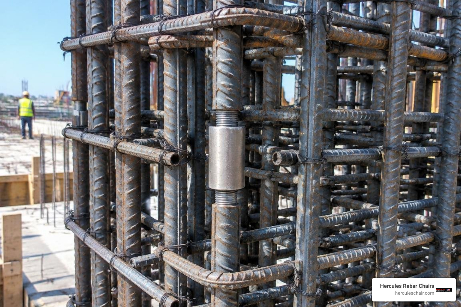
Positional systems use an extended right-hand/left-hand internal thread or a fully threaded run-out on one bar. The coupler sleeve is screwed entirely onto one bar, the second bar is brought into axial alignment, and the coupler is rotated back over both bars simultaneously to pull them tight.
These systems are essential for:
- Segmental Pours: Using mechanical lap and dowel bar splicers embedded flush against formwork eliminates protruding dowel bars, protecting formwork from drill damage and enhancing jobsite safety.
- Transition Connections: Connecting differing rebar sizes (such as #11 bars transitioning to #9 bars in upper column lifts) using factory-machined reducer couplers.
- Structural Retrofits: Splicing into short starter bars exposed during concrete demolition without requiring hydro-demolition to expose long lap lengths.
Avoiding Common Mistakes in Confined Rebar Coupler Installation
Working in dense reinforcement zones increases the risk of installation errors that can jeopardize the structure:
- Cross-Threading: Forcing a misaligned threaded coupler strips the threads and severely degrades tensile capacity. If resistance is felt within the first two turns, stop, back out, and re-align.
- Incomplete Insertion: In shear-bolt or swaged sleeves, failing to butt the rebar against the center-pin reduces the embedment depth below the required two bar diameters ($2d_b$), leading to premature pull-out under load.
- Neglecting Concrete Consolidation: While understanding how mechanical couplers secure reinforcement helps eliminate lap splice congestion, couplers still increase the outer diameter of the bar assembly. Ensure adequate spacing between adjacent couplers to allow coarse aggregates to pass freely, preventing voids and honeycombing during vibration.
Quality Control, Special Inspections, and Economic Advantages
Because reinforcement splices carry primary structural loads, the International Building Code (IBC) classifies mechanical splicing as a Special Inspection item.
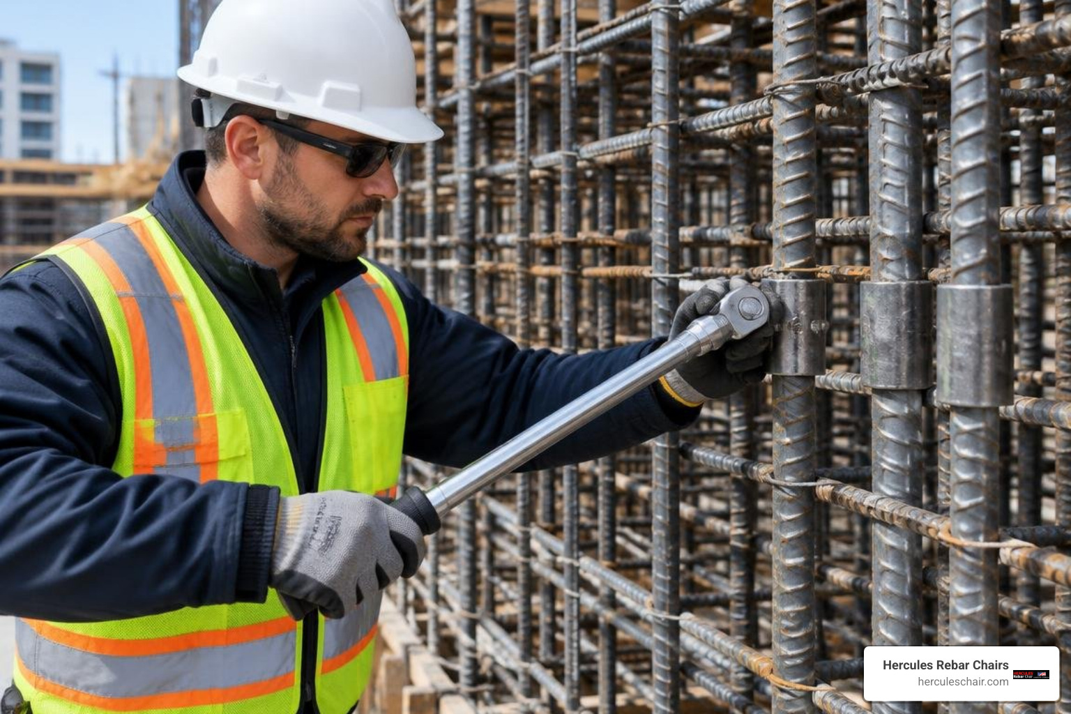
Field inspectors must verify and log:
- Coupler manufacturer certifications, mill test reports, and ICC-ES evaluation reports.
- Visual confirmation of proper bar insertion depth via center inspection ports or thread exposure counts.
- Torque wrench calibration logs or physical verification of sheared bolt heads.
- Independent laboratory tensile and cyclic slip testing per ASTM A1034 standards.
Economic and Environmental Comparison
Switching from lap splices to mechanical couplers provides clear financial and sustainability benefits:
- Direct Material Savings: Lap splices require overlapping lengths equal to 50 to 70 bar diameters, doubling steel consumption at every joint. Couplers eliminate lap length entirely, reducing total steel costs and steel wastage by up to 40%.
- Scalable Cost Advantage: While couplers reduce material costs by 5–10% on smaller bars (#5), the savings increase substantially with larger diameters—reaching up to a 140% cost advantage on #10 and #11 bars.
- Carbon Footprint Reduction: Manufacturing reinforcing steel produces roughly 9.2 times more embodied carbon ($ECO_2$) per ton than concrete. Eliminating overlapping lap steel reduces splicing-related embodied carbon by over 80%.
Frequently Asked Questions About Mechanical Splices
What is the difference between Type 1 and Type 2 rebar couplers?
Type 1 couplers must develop at least 125% of the bar’s specified yield strength ($1.25 Ab fy$). Type 2 couplers must meet the 125% yield requirement and develop the full specified tensile strength ($f_u$) of the bar. Because Type 2 couplers ensure that ductility and bar fracture occur outside the splice sleeve, building codes require them in seismic plastic hinge zones.
Can couplers be installed if the rebar cannot be rotated?
Yes. Positional couplers, extended parallel-threaded couplers, and shear-bolt couplers are designed specifically for in-situ situations where both bars are fixed in place. Turning the coupler sleeve or tightening shear bolts locks the connection without rotating either reinforcing bar.
Why are couplers preferred over lap splices in seismic zones?
Lap splices rely completely on concrete bonding and often fail during severe cyclic earthquake loading as surrounding concrete spalls and cracks. Mechanical couplers provide a direct, continuous steel-to-steel connection that maintains load transfer independently of concrete integrity.
Conclusion
Mastering mechanical rebar splicing streamlines concrete placement, lowers material costs, and ensures structural compliance with modern seismic codes. Whether you are assembling threaded, swaged, or bolted systems, maintaining clean threads, confirming full insertion, and following precise torque specifications will ensure reliable connections every time.
At Hercules Rebar Chairs, we are committed to helping contractors and engineers build stronger concrete structures from the ground up. As America’s leading rebar chair manufacturer—with over 14 million of our signature red concrete supports installed nationwide—we know that dependable reinforcement performance starts with precise bar placement, stable elevation, and code-compliant splicing.
For complete technical specifications, sizing charts, and engineering support on modern splicing systems, explore our comprehensive guide to rebar couplers to keep your next concrete pour efficient, code-compliant, and on schedule.