

Why Mechanical Couplers for Reinforcement Steel Matter on Every Job Site
Mechanical couplers for reinforcement steel are devices that join two rebar ends together in a direct, steel-to-steel connection — no concrete required for load transfer.
Here’s what you need to know at a glance:
- What they do: Transfer tension and compression forces directly from one bar to the next
- How they differ from lap splices: Lap splices rely on the surrounding concrete to transfer load; mechanical couplers do not
- Strength advantage: Mechanical splices deliver 125% to 150% greater capacity than typical lap splice design values
- When to use them: Large-diameter bars (larger than #11), tight spaces, seismic zones, and tension members
- Key code standard: ACI 318-19 requires mechanical splices to develop at least 125% of the bar’s yield strength
- Cost impact: The added cost of mechanical splices is typically around 0.2% of total structure cost — often less than the rebar savings alone
Every concrete structure depends on its reinforcement working as one continuous system. When bars need to be joined — whether in a column, wall, or bridge deck — how you make that connection matters. A weak or unreliable splice puts the entire load path at risk.
Lap splices have been the standard for decades. But as structures get taller, seismic demands get stricter, and bar sizes get larger, lap splices start to fall short. They create congestion, require extra concrete cover, and depend on the quality of the concrete around them to do their job.
That’s where mechanical couplers come in.
I’m Jordan Harris, a licensed Professional Engineer and structural engineer with hands-on experience designing large-scale concrete structures. Through my work at T.J. Harris Company, I’ve seen how the right connection hardware — including mechanical couplers for reinforcement steel — can make or break both the schedule and the structural integrity of a pour. In this guide, I’ll walk you through everything you need to know to choose and use them correctly.
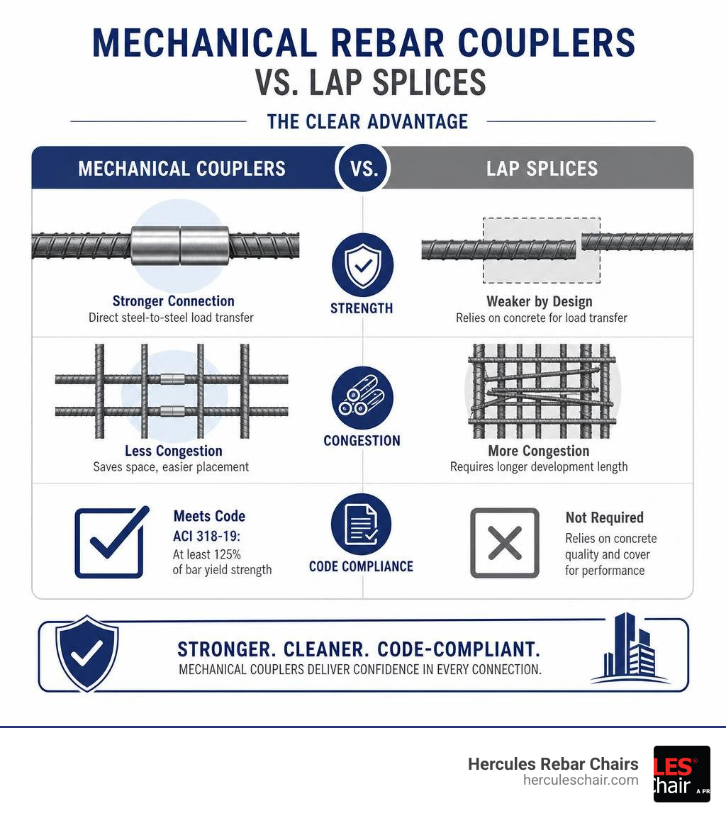
Know your mechanical couplers for reinforcement steel terms:
What Are Mechanical Couplers for Reinforcement Steel?
When we talk about reinforcing concrete, we are talking about creating a unified composite material. Concrete is fantastic under compression, but it needs steel to handle tension. For a structure to stand strong, that steel reinforcement must remain continuous.
Historically, ironworkers achieved this continuity by overlapping two pieces of rebar and tying them together with wire. While that works for basic projects, modern engineering demands a more robust solution. Mechanical couplers for reinforcement steel are structural steel components designed to mechanically join two reinforcing bars end-to-end, creating a high-strength butt joint.
Instead of relying on the surrounding concrete to transfer forces from one bar to another, these couplers establish a direct, physical connection. This ensures structural continuity regardless of the condition or presence of the concrete. Whether the concrete is cracked, undergoing seismic stress, or experiencing extreme environmental degradation, the steel-to-steel connection remains fully intact.
Understanding how these systems function is crucial for modern construction. If you want a deeper dive into the basic mechanics and terminology, check out The Contractors Guide to Rebar Couplers and Sleeves.
How Mechanical Couplers for Reinforcement Steel Differ from Lap Splices
To appreciate why mechanical splicing has become the industry standard for major infrastructure, we have to look at the physics of how forces move through concrete.
A traditional lap splice relies entirely on bond dependency. When tension is applied to Bar A, that force must pass through the surrounding concrete via friction and mechanical interlock before it can reach Bar B. This means the concrete is acting as a structural bridge. If the concrete cracks, experiences a “rock pocket” (a void where aggregate didn’t flow correctly), or degrades over time, that load path is compromised.
Furthermore, lapping rebar requires a significant amount of extra steel. This issue is compounded when working with specialized materials. For instance, building codes require up to 50% longer splice laps for epoxy-coated bars than for standard rebars because the smooth epoxy coating reduces the natural bond strength between the steel and the concrete.
Mechanical couplers eliminate this bond dependency entirely. They are engineered to deliver 125% to 150% greater capacity than typical lap splice design values. By switching to a mechanical system, you transition from a system vulnerable to concrete degradation to an uninterrupted, high-capacity load path. For an in-depth structural analysis of this transition, refer to Mechanical Splices (Couplers) in Reinforced Concrete Constructions.
Key Types of Mechanical Rebar Couplers and Their Applications
Not all job sites are created equal, and neither are all couplers. Depending on whether you are retrofitting an old bridge deck, erecting a precast parking garage, or pouring a high-rise foundation, you will need a specific coupling mechanism.
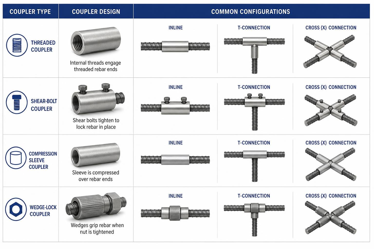
Choosing the right coupler depends on several variables: whether the rebar can be rotated, whether you have access to threading equipment, and the specific loading demands of the project. To help simplify this selection process, you can read Splicing Made Simple with These Top Rated Rebar Couplers.
Let’s break down the primary categories of mechanical couplers used across the United States today.
Threaded and Shear-Bolt Systems
Threaded systems are the most common mechanical couplers on modern jobsites. They generally fall into two categories:
- Taper Threaded Couplers: These feature a gradual taper on both the rebar ends and the inside of the coupler sleeve. This design allows for quick alignment and rapid tightening, reducing the risk of cross-threading. They are highly efficient for standard bar-to-bar connections.
- Parallel (Straight) Threaded Couplers: These require the rebar ends to be cut square and threaded with a constant diameter. While they take slightly longer to align than taper threads, they offer exceptional structural performance and are widely used in heavy civil applications.
For situations where the rebar is already cast in concrete and cannot be rotated, or where on-site threading is impractical, shear-bolt couplers are a lifesaver. These systems use a sleeve equipped with heavy-duty lock-shear bolts and internal serrated grip rails.
You simply slide the sleeve over the rebar ends and tighten the bolts. As you tighten them, the serrated rails bite into the rebar. Once the bolts reach their prescribed torque limit, the bolt heads shear off automatically. This provides an immediate, foolproof visual confirmation that the connection is fully secured. To learn more about why threaded systems are so widely adopted, take a look at Threaded Rebar Couplers and Why They Are the Industry Standard.
Swaged and Grout-Filled Systems
When dealing with massive rebar diameters or precast concrete assemblies, threaded systems aren’t always the best fit. That is where swaged and grout-filled systems come into play:
- Swaged Couplers: These systems rely on cold pressing. A heavy hydraulic press is used to squeeze a seamless steel sleeve onto the rebar ends. This cold-swaging process deforms the sleeve around the rebar’s natural deformations (ribs), creating a permanent mechanical interlock. Recent structural research, including the Finite Element Analysis of Swaged Couplers, has even validated these systems for automated, robotic reinforcement splicing on high-tech jobsites.
- Grout-Filled Sleeves: These are the gold standard for precast concrete construction. A grout-filled coupler features a wide, hollow sleeve. One end of the rebar is typically secured in the shop, while the connecting rebar is inserted into the other end on-site. High-strength, non-shrink structural grout is then pumped into the sleeve. Once cured, the grout transfers the forces between the rebar and the sleeve, making it perfect for column-to-column and wall-to-wall precast connections.
Structural Performance and Code Compliance Standards
As engineers, safety is our absolute priority. We don’t just care about how fast a system installs; we care deeply about how it performs under extreme loads.
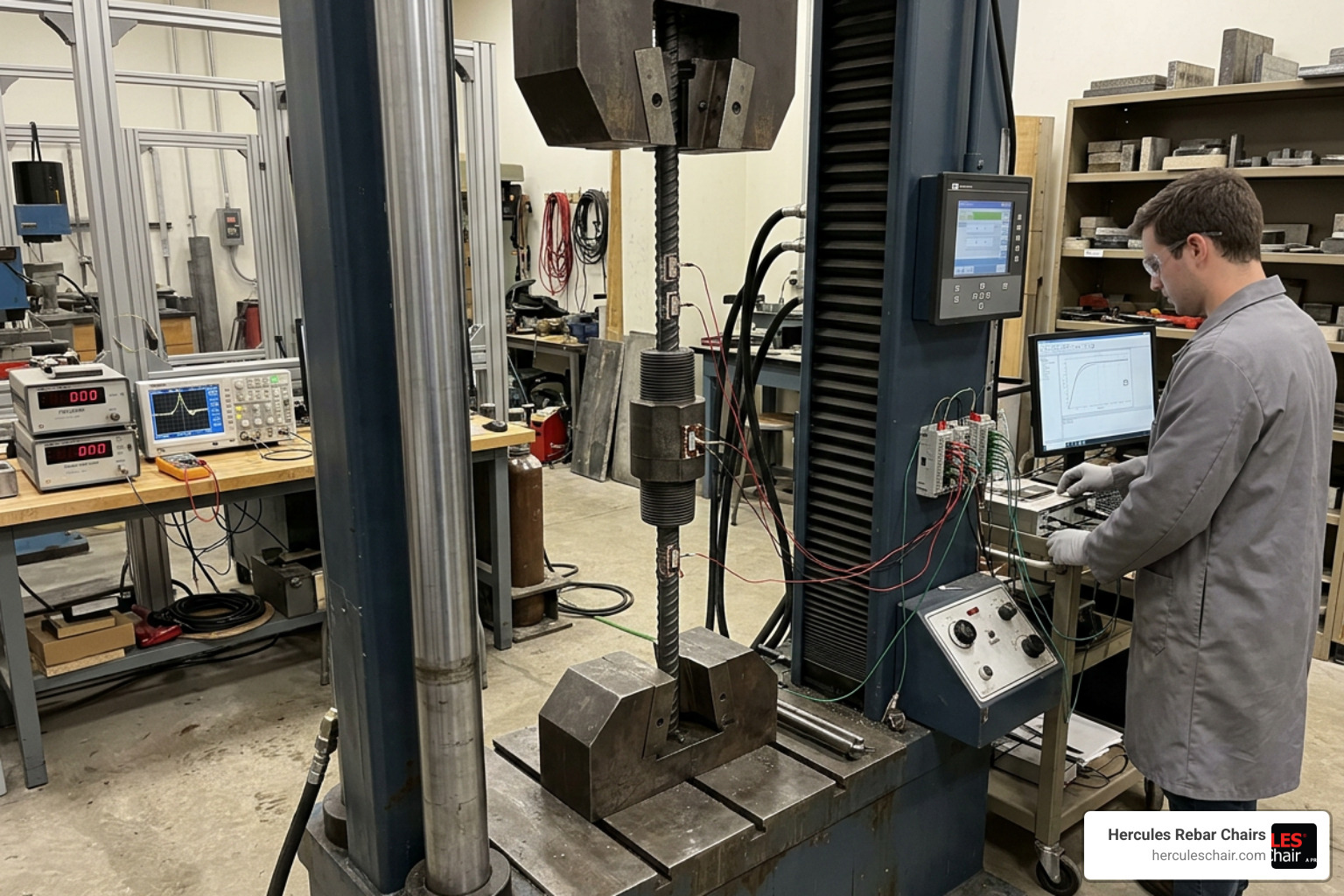
In the United States, the design and performance of mechanical splices are governed strictly by building codes, primarily the American Concrete Institute’s ACI 318-19 (and subsequent updates). To understand how to integrate these codes into your projects, you can refer to Splice It Right: Your Handbook to Mechanical Lap and Dowel Bar Splicers.
ACI 318 classifies mechanical splices into two distinct performance tiers:
- Type 1 Splices: Must develop at least 125% of the specified yield strength ($1.25 f_y$) of the bar in tension or compression. These are typically used in areas where high-ductility inelastic demands are not anticipated.
- Type 2 Splices: Must meet the Type 1 requirement (125% of yield strength) and must also develop the full specified tensile strength of the reinforcing bar. These are mandatory in high-seismic regions and are permitted anywhere within a structure, including plastic hinge zones where the steel is expected to yield during an earthquake.
Seismic, Cyclic, and Fatigue Loading Performance
In seismic zones, structures must absorb and dissipate massive amounts of energy. When an earthquake strikes, columns and shear walls undergo extreme inelastic deformation. The regions where this bending is most severe are called plastic hinges.
If you use a standard Type 1 coupler in a plastic hinge zone, the splice could fail prematurely under cyclic load reversals. Type 2 couplers are specifically engineered to withstand these intense, repeated tension-and-compression cycles without losing structural integrity.
To ensure couplers can handle these forces, they undergo rigorous testing. For example, under international standards like the IS 16172 Indian Standard Specification (which aligns closely with global ASTM and ISO testing protocols), couplers are classified based on their fatigue resistance:
- Class L (Low-Cycle Fatigue): Tested to survive low-cycle dynamic events, typically representing seismic loading.
- Class H (High-Cycle Fatigue): Subjected to grueling high-cycle fatigue tests (such as 2,000,000 cycles at a specific stress range). These are required for structures subject to constant dynamic loading, such as high-speed railway bridges, highway overpasses, and heavy industrial machine foundations.
Additionally, high-quality couplers must limit slip – the tiny amount of movement that occurs inside the coupler when a load is first applied. Under standard testing, the maximum allowable slip is restricted to a mere 0.10 mm (0.004 inches) to ensure the structure remains stiff and crack-resistant.
Approved Systems and Regulatory Listings
Before any mechanical coupler can be installed on a public highway, bridge, or high-rise building in the United States, it must be thoroughly vetted and approved by regulatory bodies.
For transportation projects, state Departments of Transportation maintain strict lists of authorized materials. The California Department of Transportation, for example, publishes the Caltrans Steel Reinforcing Couplers List. This list details exactly which coupler models, sizes, and brands are approved for use as “Service” or “Ultimate” (Type 1 and Type 2) splices on ASTM A706 and A615 reinforcing steel.
For commercial and residential buildings, structural engineers rely on ICC-ES (International Code Council Evaluation Service) evaluation reports. These reports provide independent verification that specific mechanical coupler systems comply with the International Building Code (IBC) and ACI 318 standards.
Additionally, for federally funded projects, you must ensure that your couplers meet the Build America, Buy America (BABA) Act requirements, meaning the steel must be melted and manufactured right here in the United States.
Cost-Benefit Analysis: Mechanical Couplers vs. Lap Splices
At first glance, a box of mechanical couplers looks like an added material expense compared to a bundle of tie wire. But looking only at the unit cost of the hardware is a classic project management mistake. To see a complete breakdown of how different connection systems compare financially, read A Comprehensive Guide to Comparing Rebar Connection Tools.
To get an accurate picture, we have to look at the total cost of the structure. Historically, research has shown that the additional material cost of using mechanical butt splices amounts to only about 0.2 percent of the total cost of the structure.
In return for that 0.2% investment, you unlock massive savings in steel volume, labor hours, and construction schedule. Let’s look at how the cost advantage of using a coupler instead of a traditional lap splice changes as rebar diameter increases:
| Rebar Size | Lap Splice Length (Approx.) | Steel Savings with Coupler | Cost Advantage of Coupler |
|---|---|---|---|
| #5 (16 mm) | 30 inches | Minimal | ~11% Savings |
| #8 (25 mm) | 50 inches | Moderate | ~45% Savings |
| #10 (32 mm) | 70 inches | Significant | ~140% Savings |
| #11 (36 mm) | 85 inches | Very High | Highly Cost-Effective |
| #14 & #18 | Not permitted to be lapped | Mandatory | Infinite (Only option) |
Because the required length of a lap splice is directly tied to the bar diameter, lapping large bars wastes an enormous amount of expensive steel. By using a mechanical coupler, you cut out that wasted overlap entirely. This translates directly to less weight, lower shipping costs, and faster crane cycle times.
On-Site Installation, Detailing, and Quality Control
Installing mechanical couplers for reinforcement steel on-site is highly efficient, but it requires strict adherence to quality control (QC) protocols to ensure the structural integrity of the build.
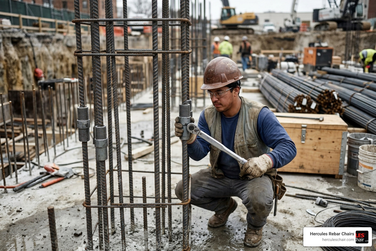
When detailing concrete members, you must account for the physical size of the coupler. Because couplers have a larger outer diameter than the rebar itself, you must measure all concrete cover and spacing requirements from the outermost surface of the coupler sleeve, not the bar. Failure to do this can lead to thin concrete cover, resulting in premature moisture penetration and corrosion.
For a comprehensive layout of on-site installation rules, check out Rebar Couplers: Your Ultimate Guide to Connecting Steel Strong.
Key on-site QC checks include:
- Thread Protection: Keep protective plastic caps on threaded rebar ends until the moment of connection to prevent rust, dirt, and concrete splatter from damaging the threads.
- Torque Verification: For threaded systems, use a calibrated torque wrench to verify that the couplers are tightened to the manufacturer’s specified torque.
- Visual Inspections: For shear-bolt systems, verify that every single bolt head has sheared off. For threaded systems, ensure that no excessive threads are visible outside the coupler sleeve.
- Special Inspections: Depending on the jurisdiction and seismic design category, an independent special inspector may need to verify the grade, size, and torque of the installed couplers before concrete placement.
Best Practices for Detailing and Staggering Mechanical Couplers for Reinforcement Steel
To prevent stress concentrations in a single plane of your concrete member, structural detailing guidelines heavily emphasize staggering your splices. When many couplers are lined up in a single row, it can create a plane of weakness and make it difficult for concrete aggregate to flow smoothly between the bars.
Here are the best practices we recommend on every jobsite:
- Seismic Staggering: In seismic design regions, building codes require a minimum of 30 inches (750 mm) of separation between adjacent mechanical splices. This staggering distributes the stiffness of the couplers and ensures the member can yield evenly during an earthquake.
- Keep Out of Plastic Hinges: Whenever possible, locate mechanical splices outside of high-stress plastic hinge regions (such as the bottom and top of columns, or near beam-column joints) unless you are using certified Type 2 couplers.
- Avoid Large Offset Splices: Offset splices (where the rebar is bent to transition to a different alignment) should not be used with bar sizes larger than #5 (16 mm) unless extensive testing proves they satisfy the project’s specific performance criteria.
- Corrosion Protection: If you are working with epoxy-coated or galvanized rebar, ensure that the couplers match the corrosion resistance of the bars. Any exposed steel threads or damaged coatings must be meticulously touched up with a compatible epoxy touch-up compound before the pour.
Frequently Asked Questions about Mechanical Rebar Splicing
What is the difference between Type 1 and Type 2 couplers?
Type 1 couplers are designed to develop at least 125% of the specified yield strength of the rebar. Type 2 couplers must meet this requirement and also develop the full specified tensile strength of the rebar. Because of this extra strength, Type 2 couplers are permitted in high-seismic zones and plastic hinge regions where extreme bending and steel yielding are expected.
How do mechanical couplers reduce rebar congestion?
In heavily reinforced columns and beams, lapping rebar doubles the amount of steel in the splice zone. This high steel ratio leaves very little room for concrete to flow, often resulting in “rock pockets,” voids, and poor consolidation. Because mechanical couplers join bars end-to-end, they maintain a consistent steel ratio, allowing concrete to easily flow around the reinforcement and ensuring a solid, void-free pour.
Are mechanical couplers cost-effective for smaller bar sizes?
While the material savings on steel are less dramatic for smaller bars (like #4 or #5), couplers can still be highly cost-effective when you factor in schedule savings. For example, using positional couplers or form savers can eliminate the need to drill holes through expensive formwork for protruding dowels, saving significant labor and extending the life of your forms.
Conclusion
At the end of the day, a concrete structure is only as strong as its connections. While traditional lap splices still have their place on simple, low-load projects, mechanical couplers for reinforcement steel represent the future of high-strength, efficient, and code-compliant concrete design. They eliminate bond dependency, dramatically reduce steel congestion, and provide the robust structural continuity that modern engineering demands.
Of course, keeping your steel continuous is only half the battle. To ensure that your rebar grid remains perfectly positioned during the heavy traffic of a concrete pour, you need heavy-duty, reliable supports.
At Hercules Rebar Chairs (T.J. Harris Co.), we manufacture America’s #1 strong rebar chairs and concrete supports. Our signature red chairs are designed to save you time and money on-site while ensuring absolute code compliance. When you pair high-performance Hercules Rebar Splicers with our ultra-strong rebar chairs, you can rest easy knowing your reinforcement grid is locked in, code-compliant, and built to stand the test of time.