

Why Footing Reinforcement Details PDF Guides Are Essential for Structural Integrity
A footing reinforcement details PDF is a structured engineering document that shows how steel reinforcement bars are placed, spaced, and connected within a concrete footing. Here is a quick overview of what these documents typically cover:
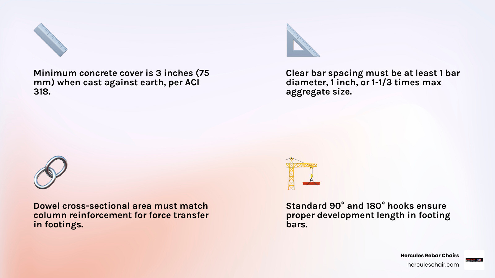
- Concrete cover requirements — minimum 3 inches (75 mm) when cast against earth (ACI 318)
- Bar spacing limits — clear space of at least 1 bar diameter, 1 inch (25 mm), or 1-1/3 times maximum aggregate size for buildings
- Dowel and lap splice details — cross-sectional area, embedment depth, and splice locations for column-to-footing connections
- Hook and bend dimensions — standard 90-degree and 180-degree hook geometry for development length compliance
- Bar support specifications — rebar chairs and supports to hold steel at the correct height during the pour
- Footing reinforcement schedules — bar lists, isolated footing sizes, combined footing layouts, and shear link requirements
These details are governed primarily by ACI 315-99 (detailing standards) and ACI 318 (building code requirements), with regional variations under IS-456, AS 2870, and other local codes.
Getting any one of these elements wrong can stop a project cold. A single detailing error on a multi-million dollar build can require field fixes between the engineer and contractor — costing time and money that no one budgeted for.
That is why having a clear, code-compliant footing reinforcement details PDF before the pour is not optional. It is the difference between a foundation that passes inspection and one that does not.
I’m Jordan Harris, a licensed Professional Engineer with a master’s degree in structural engineering and five years of hands-on experience detailing large-scale concrete foundations for major power generation projects — work that taught me exactly how much rides on a well-prepared footing reinforcement details PDF. As part of the team at Hercules Rebar Chairs, I also see how the right bar supports are what translate those PDF details into a structurally sound, code-compliant pour.
Standard Practices for Detailing Reinforced Concrete Footings (ACI 315-99 & ACI 318)
When we dive into the structural design of foundations, we must follow strict guidelines to ensure safety and constructability. Under ACI 315-99 (Standard Practice for Showing Reinforcing Steel Details) and ACI 318-14, there is a clear division of responsibility between the structural engineer and the reinforcing steel detailer. The structural drawings must show concrete dimensions, concrete cover, anchorage lengths, and the exact location and length of lap splices.
For engineers designing shallow foundations, referencing a comprehensive Spread Footing Design Guidelines | PDF is standard practice to establish base area dimensions, wide-beam (one-way) shear, and punching (two-way) shear limits. To avoid common pitfalls on-site, we recommend reading our list of Don’t Let Your Foundation Fail with These Rebar Design Tips to understand how stress concentrations impact foundation longevity.
Standard Hook and Bend Dimensions for Footing Bars
To properly develop the tensile strength of reinforcing steel within the short geometry of a footing, standard hooks are often required. A standard 90-degree or 180-degree hook provides mechanical anchorage where there is not enough straight length of concrete to fully develop the bar.
According to code standards, standard hook dimensions are calculated based on the bar diameter ($db$). For example, a 90-degree hook requires a bend with an inner diameter of at least $6db$ for #3 through #8 bars, plus a straight extension of $12d_b$ at the free end. When detailing these bends, refers to our Rebar Placement Guide to ensure your bends are physically practical and do not cause congestion during assembly.
Specifying Corrosion-Resistant Coatings
In areas with highly corrosive soils, high water tables, or exposure to deicing salts, standard black rebar will degrade over time. Engineers specify corrosion-resistant coatings, such as epoxy-coated or galvanized reinforcement, to extend the lifespan of the foundation.
When specifying these materials in your footing reinforcement details PDF, it is crucial to adjust development lengths. Epoxy-coated bars require a 20% to 50% increase in development and lap splice lengths because the slick epoxy coating reduces the mechanical bond between the steel and the concrete matrix. For a deep dive into choosing the right steel properties, check out The Essential Guide to Rebar Sizes and Grades.
Concrete Cover, Bar Spacing, and Tolerances in Footing Design
To prevent water from reaching the steel and causing spalling, structural concrete requires strict physical separation from the surrounding soil. This separation is called “clear cover.”
Maintaining correct spacing and cover during a heavy concrete pour is a major challenge. If the rebar shifts even an inch, the structural capacity of the footing drops. To understand how to prevent this, explore The Ultimate Guide to Spacing and Supporting Footing Rebar.
Concrete Cover Requirements Against Earth
For concrete cast directly against and permanently exposed to earth, both ACI 318 and international standards dictate a minimum of 3 inches (75 mm) of clear concrete cover. This ensures that minor soil movement, water intrusion, and chemical exposure do not compromise the steel.
If you are pouring a continuous foundation, you can refer to the CONTINUOUS CONCRETE FOOTING ON UNDISTURBED SOIL (FOOTING REINFORCEMENT AS PER CODE OR AS SPECIFIED) guide for visual layouts of how to maintain this 3-inch cover while dealing with uneven excavation walls.
Reinforcing Steel Supports and Bar Supports
How do we guarantee that the steel mesh stays exactly 3 inches off the ground when workers are walking on it and concrete is dropping from a pump truck? We use heavy-duty rebar supports.
Under standard detailing practices, bar supports are specified for top bars in footings and foundation mats that are 4 feet (1200 mm) or less in thickness. These supports should be spaced at an average of 4 feet (1200 mm) in each direction.
At Hercules Rebar Chairs, we manufacture the industry’s most reliable, high-strength concrete supports. Our signature red, USA-made rebar chairs are designed to support heavy loads without crushing, ensuring your steel remains exactly where the engineer specified. To find the right support for your project, consult The Ultimate Guide to Footer Stand Options and read A Practical Guide to Rebar Footing Stands to plan your layout.
Dowel Placement and Lap Splices for Column Footings
Columns carry massive axial loads that must be transferred smoothly down into the footing. This load transfer is accomplished through vertical steel dowels that project out of the footing and lap splice with the column’s vertical bars above.
To ensure this connection is executed safely, field crews must follow precise installation guidelines, which you can read about in How to Install Rebar in Footings the Right Way.
Detailing Dowels for Column Offsets
When detailing dowels for column connections, the total cross-sectional area of the dowels must at least equal the cross-sectional area of the vertical steel inside the column above. These dowels must extend both above and below the joint to meet the required development lengths.
In cases where the depth of the footing is too shallow to satisfy the standard development length ($L_d$) of a large dowel, we must decrease the diameter of the dowels and increase their total quantity to maintain an equivalent steel area. If you run into tight spatial constraints, you can explore alternative connection methods in Rebar Couplers Your Ultimate Guide to Connecting Steel Strong.
Lap Splice Limitations and Mechanical Couplers
A critical rule in structural detailing is that lap splices are not permitted for No. 14 and No. 18 bars in tension. The only exception is when transferring compression forces to smaller-sized dowels anchored into building footings.
Because of these limitations, high-load projects rely on mechanical connections. To understand how these heavy-duty mechanical joints operate, read Threaded Rebar Couplers and Why They Are the Industry Standard.
How to Read and Organize a Footing Reinforcement Details PDF
For a contractor on-site, a structural drawing can look like a confusing maze of lines, symbols, and notes. Learning to read a footing reinforcement details PDF is essential to avoiding costly field errors.
If you are new to interpreting these documents, start with Building Strong Foundations Formwork and Reinforcement Essentials for a solid foundation in drawing terminology. For a real-world example of structural schedules, you can view this Footing Reinforcement Details | PDF | Engineering | Economic Sectors document to see how engineers format schedules.
Key Components of a Footing Reinforcement Details PDF Schedule
A professional structural drawing includes a “Footing Schedule” table. This table summarizes the physical dimensions and reinforcement required for every footing on the job site.
| Footing Mark | Dimensions (L x W x D) | Bottom Reinforcement (X-Dir) | Bottom Reinforcement (Y-Dir) | Top Reinforcement (If Required) | Dowel Requirements |
|---|---|---|---|---|---|
| F1 (Isolated) | 5’0″ x 5’0″ x 18″ | #5 @ 8″ O.C. | #5 @ 8″ O.C. | N/A | 4 x #6 (Match Column) |
| F2 (Isolated) | 7’6″ x 7’6″ x 24″ | #6 @ 6″ O.C. | #6 @ 6″ O.C. | N/A | 6 x #8 (Match Column) |
| CF1 (Combined) | 18’0″ x 6’0″ x 30″ | #8 @ 6″ O.C. (Long) | #6 @ 8″ O.C. (Short) | #5 @ 12″ O.C. (Top continuous) | 8 x #8 (At Column Locations) |
Downloading and Implementing a Footing Reinforcement Details PDF on Site
Once the structural engineer approves the design, the specialist concrete contractor produces highly detailed “shop drawings” or “placement drawings” for the field crew.
To understand how contractor detailing can improve buildability and speed up your project schedule, consult A Guide to Contractor Detailing of Reinforcement in Concrete . Once your shop drawings are finalized, use our Footer Stand Placement Guide to calculate exactly how many supports you will need to keep your layout secure.
Special Detailing Conditions: Offset Columns, Bundled Bars, and Highway Structures
Not every footing is a perfect square centered directly under a single column. Real-world architectural constraints often require structural engineers to detail complex, non-standard conditions.
When working on complex residential layouts, proprietary steel solutions like SENSE 600 can help reduce total steel weight and congestion while maintaining full code compliance.
Detailing for Buildings vs. Highway Structures
The detailing rules for commercial buildings (governed by ACI 318) differ significantly from those for highway structures and bridges (governed by AASHTO).
For example, the clear spacing between parallel bars in buildings must be at least 1 bar diameter or 1 inch. In cast-in-place highway bridges, that minimum spacing increases to 1.5 bar diameters or 1.5 inches to allow larger aggregate concrete mixes to flow easily through highly congested cages. For an overview of how wall and footing reinforcement changes with structural load, review Table 1 Required Reinforcement for Varying Height Basement Walls* .
Bundled Bars and Offset Column Faces
When column loads are exceptionally high, there may not be enough physical space to fit individual vertical bars. In these scenarios, detailers use “bundled bars” — groups of up to four parallel bars tied in direct contact. Bundled bars require special development length calculations (typically increased by 10% for a 3-bar bundle and 20% for a 4-bar bundle) and require extra ties to prevent buckling.
When column faces are offset from the footing center, the vertical steel must bend to transition across the offset. The slope of this inclined offset portion must not exceed 1 in 6. Additionally, we must place transverse ties within 6 inches of the bend points to resist the outward lateral thrust forces generated at the bend. To see how these offset loads impact slab-on-grade systems, read The Pros and Cons of Slab on Grade Foundations.
Frequently Asked Questions about Footing Reinforcement
What is the standard clear cover for concrete footings?
The standard clear cover for concrete footings cast directly against and permanently exposed to earth is 3 inches (75 mm). This is a strict requirement under ACI 318 to prevent soil moisture, acids, and salts from penetrating the concrete and corroding the steel reinforcement.
Can No. 14 and No. 18 bars be lap spliced in footings?
No, standard lap splices are not permitted for heavy No. 14 and No. 18 bars because the transfer of high tensile forces over a simple lap joint is highly unreliable. The only exception is when transferring compression forces to smaller dowels that are anchored into footings for buildings. Otherwise, you must use mechanical couplers or welded splices.
How are bar supports specified for thick foundation mats?
For foundation mats and footings that are 4 feet (1200 mm) or less in thickness, bar supports are detailed for the top steel layer only. These supports should be spaced at an average of 4 feet (1200 mm) in each direction. For mats thicker than 4 feet, standard plastic or wire chairs are typically replaced with custom fabricated structural steel standees to ensure stability under heavy construction loads.
Conclusion
At the end of the day, a footing reinforcement details PDF is only as good as its physical execution in the field. You can have a mathematically perfect, code-compliant drawing, but if your steel shifts, sags, or touches the dirt during the concrete pour, your foundation is compromised.
That is why we engineered Hercules Rebar Chairs. As America’s #1 choice with over 14 million units sold across the USA, our heavy-duty, easily identifiable red concrete supports are built to save you time and money while ensuring absolute code compliance.
Don’t let a detailing error or a crushed support ruin your next pour. To learn more about mastering your rebar installations, read our comprehensive guide on Foundation Strong Mastering Rebar Placement for Lasting Concrete and equip your crew with Hercules Rebar Chairs today.