

Structural Functions and Primary Types of Bar Splices
Every concrete structure relies on a continuous internal network of reinforcing steel to carry tensile and flexural forces. Because steel mills produce rebar in standard lengths—typically 20 to 40 feet for light bars and up to 60 feet for larger bar sizes—field splicing is unavoidable.
When a reinforcing bar reaches its end, the stress carried by that bar must pass cleanly to the next without creating weak points or localized concrete failure. Bar splices serve as critical force-transfer bridges. They transfer tensile or compressive stress across adjacent steel elements, ensuring the structure acts monolithically.
| Splice Type | Force Transfer Mechanism | Main Advantages | Key Limitations |
|---|---|---|---|
| Lap Splice | Indirect via surrounding concrete bond shear | Simple; requires no specialized equipment or bar-end tools | High rebar congestion; code-restricted on #12+ bars |
| Mechanical Splice | Direct alignment via high-strength steel coupler sleeve | Reduces congestion; handles dynamic loads; mandatory for large bars | Requires mechanical couplers and installation tools |
| Welded Splice | Direct metal fusion through arc or pressure welding | Compact alignment; eliminates overlapping steel | High labor/inspection cost; risk of brittle failure if welded incorrectly |
Lap Splicing Method
Lap splicing is the most traditional and widely used connection method in cast-in-place concrete. Instead of joining the ends of two bars directly, the bars are positioned parallel to one another over a calculated distance.
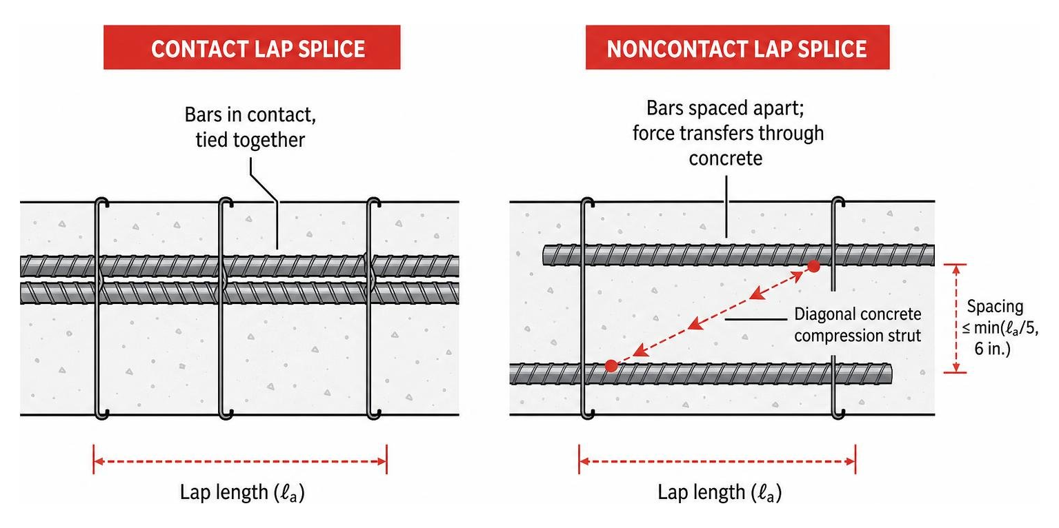
Lap splices fall into two main configurations:
- Contact Splices: The lapped bars sit side-by-side and are tied together using wire. This prevents movement during the concrete pour.
- Noncontact Splices: The bars are spaced apart laterally. Force transfers through a diagonal concrete compression strut between the two bars. ACI rules require noncontact lap splices to be spaced no farther apart than one-fifth of the required lap length, or 6 inches, to avoid zigzag cracking in the concrete matrix.
Because lap splices depend on concrete bond stress, the quality of the concrete and proper rebar placement are vital. If bars are shifted during concrete placement, the load path is compromised.
Mechanical Splicing Method
As structural designs call for heavier rebar densities and higher seismic resilience, mechanical splicing has become an industry standard. Mechanical splices use sleeve devices—often called rebar couplers—to connect bar ends in line. To learn more about these mechanical systems, read our deep-dive on Reinforcing Bar Couplers: Making Ends Meet in Concrete Construction.
Mechanical couplers eliminate steel overlap, reducing concrete congestion in narrow beam-column joints and heavily reinforced wall foundations. By keeping the load transfer entirely within high-strength steel components, mechanical splices maintain end-to-end alignment and optimize structural ductility under heavy tension and dynamic loads.
Welded Splicing Method
Welded splices join rebar ends directly using arc welding or gas pressure welding. All structural welding on reinforcing steel must strictly comply with AWS D1.4 (Structural Welding Code – Reinforcing Steel).
Despite offering a slim profile, field welding involves notable drawbacks:
- Weldability Requirements: Standard ASTM A615 Grade 60 steel contains carbon equivalents that make field welding difficult without specialized preheating protocols. ASTM A706 low-alloy steel is required for structural welding.
- High Costs: Field welding requires certified welders and mandatory non-destructive testing (NDT), making it one of the most expensive splicing solutions.
- Brittle Failure Risks: Tack welding crossing bars—a practice often attempted by inexperienced crews to hold steel in place—causes localized heat-affected zones that lead to brittle fatigue failure under load.
Design Calculations and Structural Rules for Lap Splicing
Calculating lap splice length is not a guess; it requires applying precise building code provisions set forth in ACI 318. The fundamental goal of a tension splice is to develop the full yield strength ($f_y$) of the reinforcing bar without causing the surrounding concrete to split or crack.
Where:
- $f_y$ = Specified yield strength of steel reinforcement (psi)
- $f_c’$ = Specified compressive strength of concrete (psi)
- $d_b$ = Nominal diameter of the reinforcing bar (in.)
- $\alpha, \beta, \gamma, \lambda$ = Modification factors (bar location, coating, size, and lightweight concrete factors)
Understanding how to calculate these values ensures structural safety. You can explore calculation steps in Splice It Right: Your Handbook to Mechanical, Lap, and Dowel Bar Splicers.
Standard Guidelines for Lap Bar Splices
Under ACI codes, tension lap splices are categorized into two classes based on the stress level in the steel and the percentage of reinforcement lapped at a single location. For step-by-step guidance, see How to Master the Rebar Splice Length Formula.
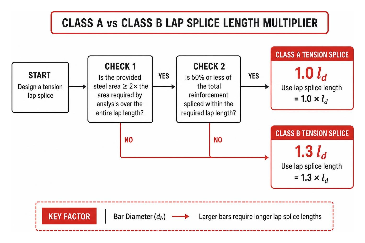
- Class A Tension Splices ($1.0 l_d$): Permitted only when the area of steel provided is twice the area required by analysis over the entire length of the splice, and 50 percent or less of the total reinforcement is spliced within the required lap length.
- Class B Tension Splices ($1.3 l_d$): Required for all structural locations where the steel area ratio is less than two, or where more than 50 percent of the bars are spliced at one section. Class B splices are the standard default used by structural detailers to ensure safety.
Key factors that directly increase required lap splice lengths include:
- Bar Diameter ($d_b$): Larger bars require deeper embedment lengths to transfer load.
- Concrete Compressive Strength ($f_c’$): Lower-strength concrete yields longer required lap lengths due to lower bond shear capacity.
- Epoxy Coatings: Epoxy-coated rebar requires up to a 50 percent increase in lap length because the smooth coating reduces mechanical friction against the concrete.
- Bar Location: Top-cast horizontal bars (with more than 12 inches of fresh concrete poured below them) require a 1.3 multiplier due to air and water settlement under the bar during consolidation.
Compression Splices and Large-Diameter Bars
Compression lap splices behave differently than tension splices because force transfers partly through direct steel-on-steel end bearing.
For Grade 60 rebar in compression where $fc’ \ge 3000 \text{ psi}$, the lap length ($ls$) is calculated as:
$$ls = 0.0005 \cdot fy \cdot db \quad \text{(for } fy \le 60,000 \text{ psi)}$$
For Grade 60 steel, this equals $30 db$. However, if the concrete compressive strength ($fc’$) is less than 3000 psi, the calculated lap length must be multiplied by $1.333$. ACI codes enforce a strict absolute minimum compression lap length of 12 inches.
Compression-only splices also require strict field preparation. Bar ends must be saw-cut within $1.5^\circ$ of square to the longitudinal axis to ensure full bearing contact across the interface, fitting within an assembly tolerance of $3^\circ$ during field erection.
The No. 11 Bar Limit and Noncontact Hooked Bars
A crucial structural rule under ACI 318-19 is that lap splices are strictly prohibited for bars larger than No. 11 (#36) in standard cast-in-place structural elements. Bars such as No. 14 (#43) and No. 18 (#57) possess immense cross-sectional area; lapping them would demand excessive lap lengths, creating high radial splitting forces in the concrete. Large-diameter bars must be spliced using mechanical couplers or full-penetration welds.
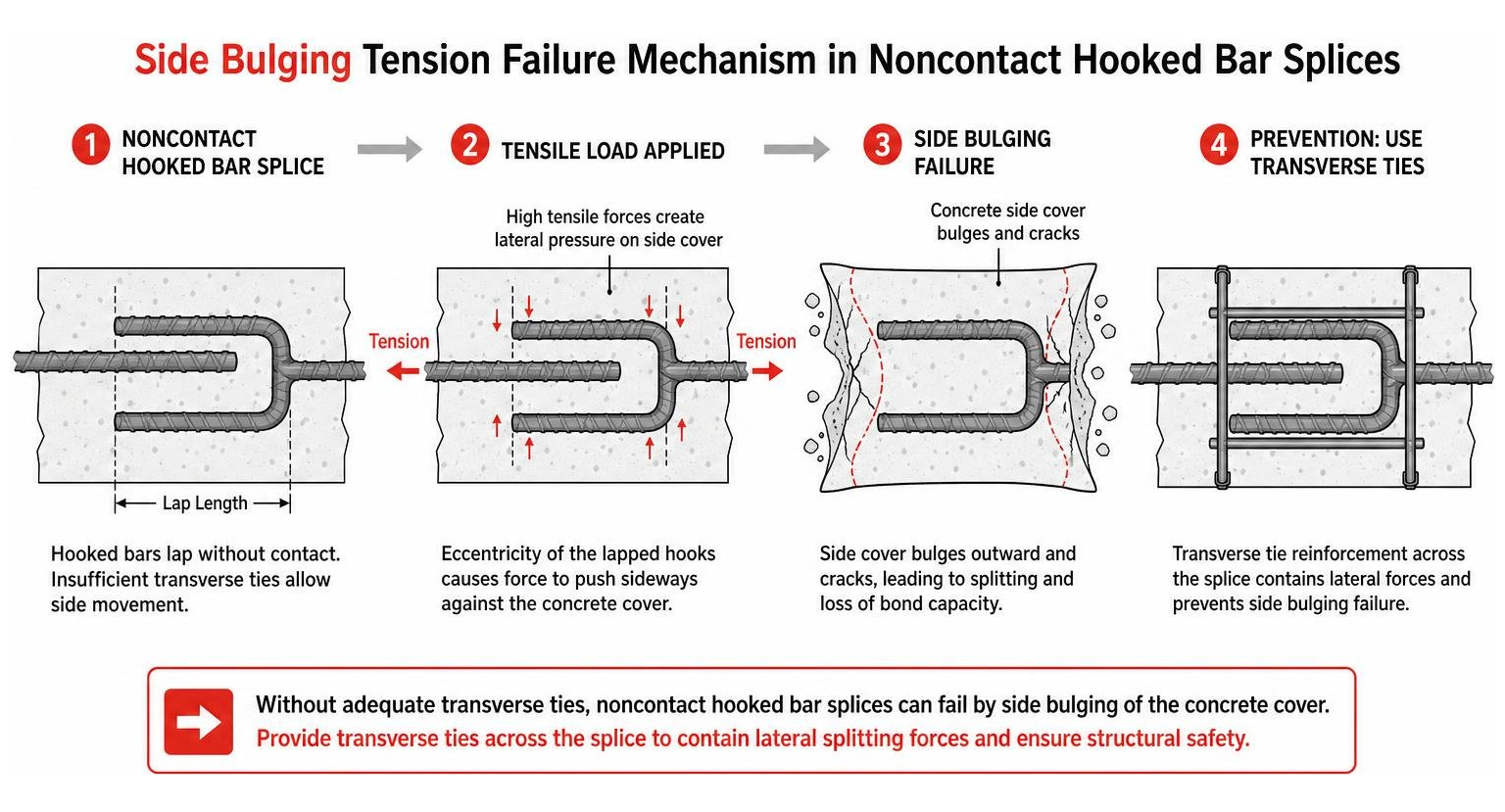
When noncontact hooked bar lap splices are used in precast closure joints or bridge pier caps, recent research highlights a critical failure mode: hook side bulging. Because of eccentricity between lapped hooked bars without adequate transverse ties, high tensile forces push sideways against thin concrete side cover. Design engineers must include transverse tie reinforcement across hooked bar laps to contain these lateral splitting forces.
Mechanical Couplers: Types, Classifications, and Code Standards
As concrete building designs become more complex, mechanical couplers have transitioned from a specialized alternative to a primary construction solution. Mechanical splices are governed by building code performance metrics defined under ACI 318-19. Read our article on How Mechanical Couplers Keep Your Reinforcement Steel Together for an in-depth breakdown.
ACI 318-19 classifies mechanical splices into two distinct structural tiers:
- Type 1 Mechanical Splices: Must develop at least 125 percent of the specified yield strength ($1.25 f_y$) of the spliced rebar in tension or compression. Type 1 splices are permitted anywhere in a structure except inside plastic hinge zones or within twice the member depth ($2h$) from column/beam joint faces in seismic framing.
- Type 2 Mechanical Splices: Must meet the 125 percent yield requirement and develop the full specified ultimate tensile strength ($f_{ut}$) of the bar. Because Type 2 splices withstand strain-hardening under cyclic load reversals, building codes permit their placement anywhere within structural members, including plastic hinge regions.
Threaded and Swaged Mechanical Systems
Mechanical couplers are manufactured in several structural styles tailored to specific field conditions. For details on industry preferences, read Threaded Rebar Couplers and Why They Are the Industry Standard.
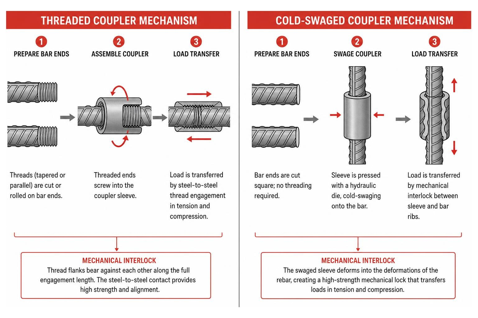
- Taper-Threaded Couplers: Feature precision-machined conical threads on the bar ends that thread into a matching sleeve. The taper provides self-aligning engagement and prevents cross-threading during high-speed field installation.
- Straight-Threaded Couplers (Upset vs. Non-Upset): Non-upset straight systems cut threads directly into the bar stem, slightly reducing the effective net cross-sectional area. Upset straight systems pre-forge (upset) the rebar ends cold or hot before thread cutting, ensuring the cross-sectional area at the root of the thread equals or exceeds the unthreaded bar area.
- Rolled Thread Parallel Systems: Advanced mechanical systems roll parallel threads directly onto cold-prepared bar ends. Rolled threads displace steel rather than cutting it away, retaining 100 percent of the bar’s full cross-sectional strength without requiring upsetting operations.
- Cold-Swaged Sleeves: Heavy-walled steel sleeves placed over plain rebar ends and pressed using a hydraulic die press. The sleeve deforms into the valleys between rebar deformations, creating a mechanical interlock without requiring pre-threading.
- Parallel UNC Threaded Dowel Systems: Ideal for staged pours and slip-form construction. A threaded socket coupler attaches to formwork; after the formwork is removed, a secondary threaded dowel screws into the flush-mounted coupler, eliminating formwork drilling.
Grout-Filled and Shear Screw Sleeve Couplers
Specialized field scenarios require mechanical connections that work without pre-threading or shop-end forging equipment. Learn more in The Contractor’s Guide to Rebar Couplers and Sleeves.
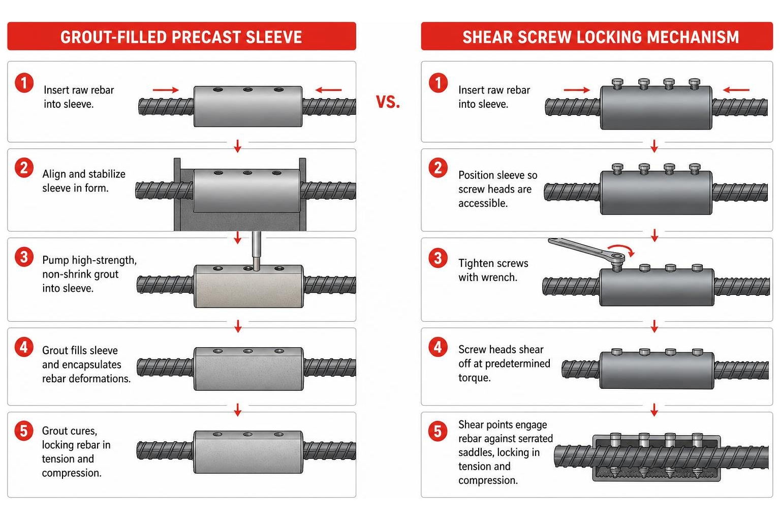
- Grout-Filled Coupling Sleeves: Widely used in precast concrete construction, such as joining precast wall panels and bridge column closure joints. One or both ends of the sleeve accept raw rebar; high-strength, non-shrink cementitious grout is pumped inside to lock the bar deformations in place.
- Shear Screw Coupling Sleeves: Feature series of shear-bolts arranged along a steel sleeve containing internal serrated saddle strips. Contractors slide the raw rebar ends into the sleeve and tighten the bolts with a wrench until the bolt heads shear off at a predetermined torque value. The bolt points force the rebar into the internal serrated rails, locking the bar in tension and compression without specialized field threading equipment.
Seismic Design, Field Installation, and Quality Control
When structures endure dynamic loads—such as earthquakes or severe wind reversals—bar splices must handle high plastic strains without failing.
Seismic Compliance for High-Stress Bar Splices
Under severe lateral building drift, reinforced concrete beams and columns develop high moment demand near member intersections, forming plastic hinge regions where reinforcement yields in alternating tension and compression.
- Type 1 Restriction: Standard Type 1 mechanical splices cannot be placed inside plastic hinges or within a distance equal to twice the member depth ($2h$) from joint faces, because their ultimate strength capacity ($1.25 f_y$) may be reached during localized yielding.
- Type 2 Compliance: Type 2 full-mechanical splices meet stringent ductile strain standards, allowing them inside plastic hinge zones under ACI 318 Section 18.
- Mandatory Staggering: In high-seismic designs, building codes require staggering adjacent bar splices by a minimum of 30 inches (750 mm) longitudinally along the reinforcement cage. Staggering avoids creating concentrated planes of rigidity, allowing the surrounding concrete to distribute micro-cracking evenly.
Installation Best Practices, Tools, and Cost Analysis
Selecting between traditional lap splicing and high-performance mechanical couplers involves evaluating material costs, site labor, and schedule efficiency. For a comparison of installation gear, review A Comprehensive Guide to Comparing Rebar Connection Tools.

- Labor-Saving Automation: Spinning threaded rebar into couplers manually using pipe wrenches can slow down placement. Specialty tool attachments—such as impact-wrench-driven bar spinners—allow ironworkers to spin threaded rebar into couplers in seconds, reducing back strain and speeding up production.
- Material Savings on Large Steel: While a lap splice requires throwing away several feet of overlapping steel per connection, a mechanical coupler uses a single compact sleeve. The material cost advantage of mechanical splicing scales drastically with larger bar sizes—saving roughly 11 percent on #5 bars and up to 140 percent in overall steel costs on #10 bars and larger.
- Coated Bar Economics: Building codes mandate up to 50 percent longer lap lengths for epoxy-coated or galvanized rebar to offset reduced surface friction. Using mechanical couplers with matching epoxy or galvanized coatings eliminates long overlapping bars, saving steel tonnage on bridge decks and marine foundations.
The Crucial Role of Rebar Supports
No bar splice can perform as designed if the steel cage settles, shifts, or sags against the mud slab or formwork during concrete placement. Mechanical couplers add concentrated weight to the rebar mat, while lap splices double the local steel weight over the splice length.

At Hercules Rebar Chairs, we manufacture heavy-duty, high-density concrete supports engineered to maintain precise steel elevation under heavy cage loading. As “America’s #1” choice—with over 14 million units sold across all 50 states—our bright red rebar chairs ensure your spliced cages maintain code-required clear cover. Proper vertical support prevents concrete cover failure, corrosion ingress, and concrete spalling around heavy spliced joints.
Frequently Asked Questions About Construction Splicing
When are mechanical splices required over traditional lap splices?
Mechanical splices become mandatory under ACI building codes whenever structural plans specify reinforcing bars larger than No. 11 (#36), such as No. 14 (#43) and No. 18 (#57) bars. Additionally, mechanical couplers are specified when heavy rebar congestion prevents concrete aggregate from flowing around overlapped bars, in high-seismic moment frames requiring ductile Type 2 performance, and in staged construction where protruding dowels would damage rebar formwork. Find more details in Rebar Couplers: Your Ultimate Guide to Connecting Steel Strong.
What is the difference between Class A and Class B tension lap splices?
The difference lies in their structural safety factor multiplier based on stress levels and splice locations:
- Class A Lap Splice ($1.0 l_d$): Permitted only when the rebar area provided is at least double the design area over the splice length and no more than 50 percent of the total bars are spliced at that section.
- Class B Lap Splice ($1.3 l_d$): Increases the development length requirement by 30 percent. Class B is required when the steel ratio is less than two, or when more than 50 percent of the bars are lapped at the same point.
What is the distinction between ACI 318 Type 1 and Type 2 mechanical splices?
A Type 1 mechanical splice must develop a minimum tensile strength equal to 125 percent of the specified yield strength ($1.25 fy$) of the bar. A Type 2 mechanical splice must meet the 125 percent yield requirement plus 100 percent of the bar’s ultimate specified tensile strength ($f{ut}$). Because Type 2 splices withstand strain-hardening under seismic reversals, they are permitted inside plastic hinge zones, whereas Type 1 splices are strictly prohibited in those regions.
Structural Reliability and Site Success
Choosing the right bar splices requires balancing code compliance, structural load paths, seismic demands, and site labor efficiency. Whether you specify traditional Class B lap splices on lighter slab mats or mechanical couplers on heavily congested column cages, maintaining proper alignment and code-required concrete cover is essential. Learn how to simplify your next project with Splicing Made Simple with These Top-Rated Rebar Couplers.
By pairing properly calculated bar connections with robust concrete supports like Hercules Rebar Chairs, engineering and site placement crews ensure that reinforcement stays locked in position throughout the pour, delivering decades of structural performance.