

Rebar Slab Basics: What Matters Most
A rebar slab is a concrete slab reinforced with steel bars. Concrete handles compression well; rebar helps it resist tension and keeps cracks from widening. For a sound pour, follow the approved plans for bar size, spacing, and depth. Tie the grid and support it on chairs so the steel stays in place as concrete is poured. Do not leave rebar on the ground or lift it by hand during the pour.
The right layout depends on the slab’s loads, thickness, soil, and local code. Rebar helps a slab perform, but it does not replace a firm base, proper joints, or good curing.
I’m Jordan Harris, a Tennessee-licensed structural engineer who spent five years working on large concrete and steel projects. At Hercules Rebar Chairs, I bring that experience to the practical details that keep a rebar slab properly supported.
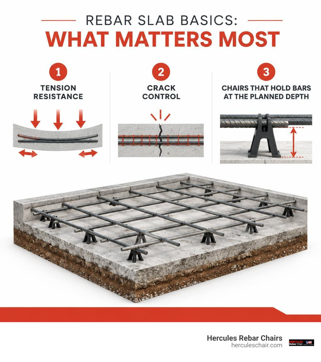
Understanding Slab Reinforcement: Why Concrete Needs Steel
Concrete is a remarkable building material, but it possesses an inherent structural limitation: while it exhibits exceptional compressive strength, its tensile strength is only about 10% to 15% of its compressive capacity. When heavy vehicles park on a driveway, heavy machinery operates in a warehouse, or ground soil shifts beneath a foundation, the slab bends. Bending creates internal tension. Without reinforcement, unreinforced concrete will crack and pull apart under minimal flexural stress.
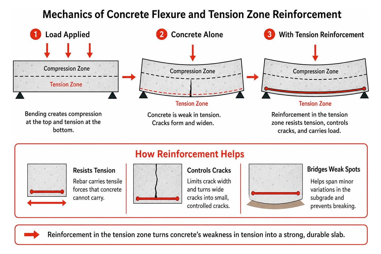
Beyond structural loads, concrete naturally undergoes volume changes throughout its life cycle. As fresh concrete cures and sheds free water, it shrinks. If this shrinkage is restrained by friction against the subgrade or adjacent structures, high tensile stresses develop. Temperature swings cause ongoing expansion and contraction cycles. Reinforcement distributes these stresses throughout the matrix, transforming wide structural fractures into controlled, hairline micro-cracks.
Subgrade settlement presents another challenge. No soil bed is completely uniform. Variations in moisture, soil density, or organic matter can cause localized voids beneath a pad. Steel reinforcement acts as an internal bridge, spanning weak spots in the subgrade to prevent differential settlement from snapping the slab. Mastering proper concrete slab support methods ensures the steel remains exactly where structural physics dictates it must be to carry these loads.
Rebar Slab vs. Wire Mesh: Choosing the Right Reinforcement
Builders often debate whether to reinforce a pad with deformed steel rebar or welded wire reinforcement (WWR), commonly called wire mesh. While both provide tensile reinforcement, their structural capacity, physical rigidity, and installation mechanics differ significantly.
Deformed steel rebar (typically ASTM A615 Grade 60) provides substantial flexural load-bearing capacity. Its raised ribs mechanical interlock tightly with the surrounding aggregate matrix. This makes rebar the standard for driveways, foundation slabs, garage floors carrying vehicle traffic, and heavy commercial pads.
Welded wire mesh consists of a grid of cold-drawn steel wires welded at intersections (such as a 6×6-inch pattern using 10-gauge wire). Mesh functions primarily as secondary reinforcement for crack control and aggregate interlock in lighter-duty applications, such as 4-inch pedestrian walkways and residential patios. Because wire mesh rolls are flexible, maintaining their elevation during concrete placement is notoriously difficult. Mesh sheets often get trampled to the bottom of the pour, rendering them ineffective. Reviewing specific reinforcement requirements for concrete slabs helps identify which material fits your target load profile.
| Feature / Metric | Deformed Steel Rebar (Grade 60) | Welded Wire Mesh (WWR) |
|---|---|---|
| Primary Function | High structural flexural strength and crack containment | Secondary shrinkage and temperature crack control |
| Tensile Yield Strength | 60,000 PSI (60 ksi) | 56,000 to 70,000 PSI (smooth drawn wire) |
| Structural Rigidity | Rigid; easily tied into walk-resistant grids | Flexible; prone to sagging and displacement |
| Support Stability | Stable on dedicated chairs at 3- to 4-foot intervals | Difficult to elevate evenly across thin pours |
| Typical Applications | Garage floors, driveways, heavy equipment pads, foundations | Sidewalks, light residential patios, non-traffic slabs |
| Material Handling | Standard 20-foot rigid lengths; requires cutting/tying | Lightweight rolls or flat sheets |
Building Codes, Soil Conditions, and Structural Demands
Building codes such as the International Building Code (IBC) and standards from the American Concrete Institute (ACI 318 and ACI 360R) establish reinforcement baselines. These standards are driven by environmental and geotechnical conditions.
Soil classification plays a critical role in reinforcement design. Expansive clay soils swell significantly when wet and shrink as they dry, exerting upward heave and downward settlement forces against the bottom of a foundation. In regions with expansive clays or high plasticity index (PI) soils, structural engineers specify dense rebar grids to give the slab enough flexural stiffness to float over shifting ground.
Similarly, in northern climates where frost depth penetrates several feet, frost heave can lift the edges of a pad. Monolithic slabs—where the interior floor slab and perimeter footings are cast in a single pour—require perimeter rebar configurations to lock the slab and footings into a single rigid unit. Proper foundation preparation and soil considerations must always precede reinforcement layout to ensure long-term stability.
Engineering Your Rebar Slab: Sizing, Spacing, and Depth Factors
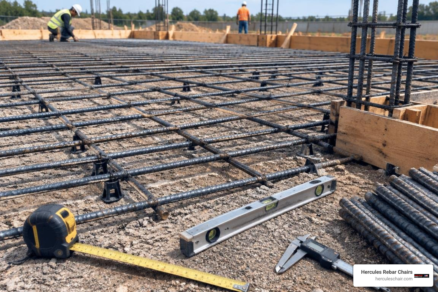
A successful reinforced slab balances steel area with concrete cross-section. Adding too little steel leaves the slab vulnerable to cracking, while adding too much steel can unnecessarily escalate material costs and cause placement issues during the pour.
Determining Bar Size and Grid Spacing
Rebar diameter is designated by bar numbers, which represent the diameter in eighths of an inch. A #3 bar is 3/8-inch in diameter, #4 is 1/2-inch (4/8), #5 is 5/8-inch, and #8 is 1 inch.
Standard residential slabs (4 to 5 inches thick) carrying light vehicle traffic commonly utilize #3 or #4 Grade 60 rebar laid out in a grid pattern spaced 12 to 18 inches on-center. For heavy residential workshops, RV pads, or commercial garage slabs (6 inches or thicker), engineers often specify #4 or #5 bars spaced on a 12-inch grid.
Heavy industrial foundations designed to support heavy manufacturing machinery often use larger sizes, such as #8 rebar on tight 6-inch centers, creating a dense structural mat that distributes high point loads across the soil. When planning heavy-duty pours, sizing rebar supports for heavy garage slabs ensures the heavy steel grid does not crush or displace its supports under crew traffic.
Elevation and Concrete Cover Requirements
For a rebar grid to function structurally, it must be embedded at the correct depth within the slab. In a standard slab-on-grade subjected to downward surface loads, the slab deflects downward, placing the bottom fibers of the concrete into tension. Therefore, structural rebar must sit in the tension zone—traditionally positioned between the bottom third and the midpoint of the slab thickness.
Equally critical is maintaining mandatory concrete cover. Concrete cover is the thickness of concrete protecting the steel from moisture, air, chlorides, and subgrade chemicals that cause oxidation and rust. According to ACI code standards:
- Concrete cast against and permanently exposed to earth requires a minimum of 3 inches of cover.
- Concrete exposed to earth or weather after forms are stripped requires 2 inches of cover for larger bars (#6 through #18) and 1.5 inches for smaller bars (#5 and smaller).
- Concrete not exposed to weather or earth (interior slabs) requires a minimum of 0.75 to 1.5 inches of cover depending on bar size and fire ratings.
Keeping rebar set back at least 2 inches from the perimeter formwork prevents moisture from penetrating the edge of the slab and reaching the steel ends. Understanding and mastering rebar placement depth protects against concrete spalling, carbonation, and premature corrosion.
Calculating Materials: Rebar Quantities and Concrete Displacement
Accurate material estimation prevents costly mid-pour delays and minimizes jobsite scrap. Rebar estimation requires calculating the total number of longitudinal and transverse runs, accounting for splice overlaps, and factoring in perimeter details.
Estimating Rebar Length, Weight, and Lap Splices
Standard pre-cut rebar sticks are supplied in 20-foot, 40-foot, and 60-foot lengths in the United States, with 20-foot lengths being standard for residential and light commercial work.
To calculate the number of rebar sticks required for a rectangular grid:
- Divide the slab length by the grid spacing (in feet) to find the number of transverse bars.
- Divide the slab width by the grid spacing (in feet) to find the number of longitudinal bars.
- Multiply the run counts by the slab dimensions to find total linear footage.
- Calculate the required lap splice allowance where continuous runs exceed stick length.
When joining rebar lengths, bars must overlap by a specified factor—typically 40 times the rebar diameter (40d) for standard Grade 60 bars in tension (though some engineering specs require 60d in critical seismic or structural connections). For #4 rebar, this requires a minimum 20-inch lap at all joints.
Weight considerations are also essential for delivery logistics. A standard #4 bar weighs 0.668 pounds per linear foot. A 20-foot stick weighs approximately 13.36 pounds. When ordering large quantities, check your vehicle capacity: a standard half-ton or three-quarter-ton pickup can quickly become overloaded when hauling full bundles of steel. Reviewing professional rebar fabrication and cutting standards helps ensure smooth jobsite staging and delivery coordination.
Concrete Volume Displacement and Slab Weight Impact
Steel rebar is dense, weighing approximately 490 pounds per cubic foot. In heavily reinforced slabs, the volume of concrete displaced by the rebar network should be subtracted from gross form dimensions to avoid over-ordering concrete.
To calculate steel displacement:
- One linear foot of #4 rebar displaces approximately 0.00136 cubic feet of volume.
- In a 1,000-square-foot slab with #4 bars on a 12-inch grid (roughly 2,000 linear feet of steel), the rebar displaces approximately 2.72 cubic feet, or about 0.10 cubic yards of concrete.
- In thick industrial slabs using #8 rebar on 6-inch double grids, steel displacement can account for 1% to 2% of total slab volume, significantly altering concrete batch plant orders.
Practical Execution: Installation, Tying, and Support Best Practices

A well-designed rebar layout is only as good as its physical installation. If reinforcement shifts, drops, or distorts during the concrete pour, the slab’s structural integrity is compromised.
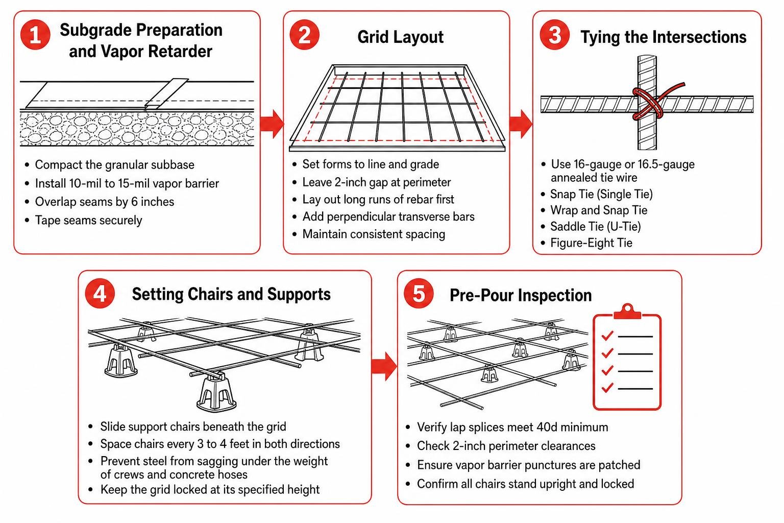
Step-by-Step Rebar Slab Installation and Support
- Subgrade Preparation and Vapor Retarder: Compact the granular subbase to uniform density. Install a heavy-duty vapor barrier (minimum 10-mil to 15-mil poly sheeting) over the base, overlapping seams by 6 inches and taping them securely to stop subgrade moisture transmission.
- Perimeter Forms and Clearance: Set forms to line and grade. Snap chalk lines on the vapor barrier or mark form stakes to guide grid spacing. Ensure a 2-inch perimeter gap between the rebar ends and form edges.
- Grid Layout: Lay out long runs of rebar first, followed by perpendicular transverse bars. Maintain consistent spacing using a marked measuring stick.
- Tying the Intersections: Secure bar intersections using 16-gauge or 16.5-gauge annealed tie wire. Common tying methods include:
- Snap Tie (Single Tie): Quick and standard for horizontal flatwork mats.
- Wrap and Snap Tie: Provides extra grip to keep bars from sliding during layout adjustments.
- Saddle Tie (U-Tie): Ideal for securing cross bars and maintaining alignment without slippage.
- Figure-Eight Tie: Used for heavy mat configurations and heavy bar sizes.
- Setting Chairs and Supports: Slide heavy-duty support chairs beneath the grid. Space chairs every 3 to 4 feet in both directions to prevent the steel from sagging under the weight of crews and concrete hoses. Placing durable rebar chairs and spacers creates a rigid, stable reinforcement cage that remains locked at its specified height throughout the pour.
- Pre-Pour Inspection: Walk the grid before the concrete truck arrives. Verify that all lap splices meet the 40d minimum, check that edge clearances are maintained, ensure vapor barrier punctures are patched, and confirm all chairs stand upright and locked.
Common Installation Mistakes and How to Prevent Failure
One of the most persistent and damaging myths in flatwork construction is the “hook-and-pull” method. Some crews place rebar directly on the ground, intending to hook the bars with a rake and pull them up into the concrete during the pour. Extensive field testing shows this practice fails: pulling rebar lifts it only temporarily, and as workers walk forward or screeds pass overhead, the bars sink right back to the dirt.
Rebar resting directly on the subgrade provides zero tensile strength to the slab and corrodes rapidly when exposed to ground moisture.
Other common installation mistakes include:
- Inadequate Chair Spacing: Spacing chairs 6 to 8 feet apart causes bars to sag between supports. When workers step on the grid, the bars bend permanently downward.
- Missing Corner Reinforcement: Reentrant (inside) corners on L-shaped or irregular slabs experience concentrated diagonal stress. Placing diagonal #4 bars across reentrant corners prevents corner cracking.
- Overtightening Tie Wire: Twisting tie wire too tightly can snap the wire or score epoxy-coated rebar, initiating early corrosion sites.
- Unstable Chairs in Soft Base: Using narrow-footed chairs on soft sand or uncompacted base allows the chairs to sink under load. Use chairs with wide, stable bases designed for flatwork.
Understanding why slabs need chair supports highlights the importance of reliable mechanical elevation over manual lifting shortcuts.
Rebar vs. Post-Tensioned Slabs: Critical Safety Differences
Modern concrete flatwork uses two primary internal reinforcement methods: conventional passive mild-steel rebar and active post-tensioned (PT) tendons. Distinguishing between these two systems is critical for jobsite safety during future building modifications, core drilling, sawing, and anchoring.
Passive Reinforcement vs. High-Tension Strands
Conventional rebar is a passive reinforcement system. The steel sits dormant in the concrete, carrying zero stress until external loads or thermal shrinkage cause the concrete matrix to strain and bend. Only when the concrete micro-cracks or deflects does the rebar engage in tension. Standard ASTM A615 Grade 60 rebar has a yield strength of 60,000 PSI (60 ksi).
Post-tensioned systems are active reinforcement systems. High-strength steel strands (typically 0.5-inch diameter, 7-wire steel cables encased in plastic sheathing) are laid in sweeping parabolic profiles inside the formwork. After the concrete cures to approximately 75% of its design strength (usually 3 to 7 days), hydraulic jacks tension these cables to approximately 150,000 to 270,000 PSI (270 ksi ultimate strength), anchoring them into the slab edges with steel wedges.
A single 0.5-inch post-tension strand carries roughly 30,000 pounds of live tensile load continuously. This puts the entire concrete slab under permanent compression, keeping the concrete tightly compressed and virtually crack-free. Post-tensioning is common in multi-family podium decks, parking structures, and large residential slabs built over expansive soil. For additional context on how steel reinforcing systems function under dynamic structural loads, see this overview on the structural performance of steel foundations.
Safe Drilling Protocols and GPR Scanning
Accidentally striking conventional rebar with a core drill bit will dull the tool and require structural review. However, striking an active post-tension cable can be catastrophic.
Severing a cable releasing 30,000 pounds of stored mechanical energy causes the steel strand to snap back explosively. The cable can burst through slab edges, rip through structural concrete, shatter anchor zones, and cause severe injury or structural collapse.
Visual indicators of post-tensioning include round grout patches on perimeter slab edges where tendon tails were cut and pocket-grouted. However, architectural finishes, stucco, and earth backfill frequently conceal these pockets. As-built plans can also be outdated or inaccurate.
For this reason, non-destructive Ground Penetrating Radar (GPR) scanning is the standard safety protocol before coring, sawing, or drilling into any commercial slab or post-1970s foundation. Certified technicians using concrete scanning with GPR can map the exact 3D coordinates, depths, and parabolic trajectories of PT tendons and embedded rebar, ensuring penetration paths remain completely clear of high-tension cables.
Frequently Asked Questions About Rebar Slabs
Is rebar always required in a concrete slab?
Building codes do not require rebar in all concrete slabs. Light, non-structural slabs on grade—such as 3.5-inch to 4-inch residential sidewalks, garden sheds, and small backyard patios—often use welded wire mesh or synthetic fiber-reinforced concrete for basic crack control.
However, rebar is required whenever the slab serves a structural purpose, supports load-bearing walls, rests on expansive or poorly compacted soils, carries heavy vehicle loads (such as garages and commercial aprons), or forms an engineered monolithic foundation.
What is the standard overlap for rebar splices?
The standard industry rule of thumb for splicing rebar in flatwork is 40 times the nominal bar diameter (40d). For a standard #4 bar (0.5-inch diameter), the required lap length is:
40 × 0.5 inches = 20 inches
Splice bars should be tied together securely with annealed wire at a minimum of two points to prevent separation during concrete discharge. In structural foundation footings subject to high seismic or dynamic loads, structural engineering plans may specify Class B tension splices reaching 60 times the bar diameter.
Can rebar sit directly on the ground during a pour?
No. Placing rebar directly on the ground or subgrade is a serious construction defect. When steel rests on the earth:
- It sits entirely outside the concrete tension zone, providing zero structural reinforcement.
- It absorbs soil moisture, starting early corrosion that causes the steel to expand and delaminate the concrete from within.
- It creates direct entry channels for moisture and soil chemicals to enter the slab.
Rebar must always be elevated and locked in place using purpose-built, non-corrosive support chairs spaced every 3 to 4 feet across the entire grid.
Conclusion
A durable concrete slab requires proper engineering, accurate material estimation, and disciplined jobsite execution. Steel reinforcement provides the tensile capacity that plain concrete lacks, transforming a brittle slab into a resilient, load-bearing structure capable of withstanding heavy loads, thermal movement, and soil shifts.
To ensure your rebar grid stays exactly where the structural plans require, prioritize reliable elevation support. Hercules Rebar Chairs (T.J. Harris Co.) manufactures heavy-duty rebar chairs and concrete supports for the construction industry. As America’s #1 support manufacturer with over 14 million units sold, our signature red chairs save time and labor costs while ensuring concrete cover compliance across every pour.
For additional planning resources and sizing formulas, explore our complete guide on calculating rebar for your slab the right way.