

Why Earthquake Resistant Rebar Chairs Matter
Choose rebar chairs that hold each bar at the cover and height shown on the structural drawings. They must stay stable as crews walk, place concrete, and compact it. Use supports suited to the weight of the steel and the surface below it, and avoid bare steel legs that could create a path for corrosion. Check spacing against the project plan; about 1 meter is a common starting point, not a rule for every pour.
That placement matters in a seismic structure. If bars sag or shift before the concrete sets, they may not have the cover or position the engineer designed. Chairs hold the reinforcement in place during the pour; properly detailed stirrups and ties, not chairs, restrain bars against buckling during an earthquake.
I’m Jordan Harris, a Tennessee-licensed structural engineer with experience on large concrete projects. At Hercules Rebar Chairs, I bring that background to the design and evaluation of earthquake resistant rebar chairs and other rebar supports.
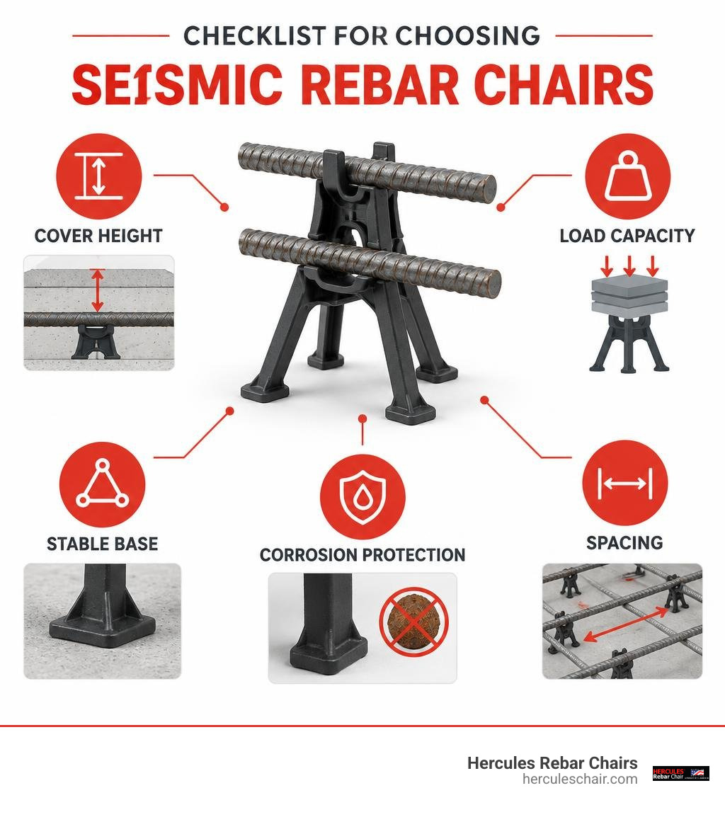
Essential earthquake resistant rebar chairs terms:
The Critical Role of Concrete Cover and Elevation in Seismic Zones
When a seismic event occurs, structural concrete undergoes severe cyclic lateral loading, reversing stresses from tension to compression in fractions of a second. To absorb and dissipate this dynamic energy without brittle collapse, reinforced concrete elements rely entirely on the composite interaction between the reinforcing steel and the surrounding concrete matrix. If steel bars are displaced even a few millimeters from their designated positions, the calculated internal lever arm changes, drastically reducing the element’s flexural capacity and ductility.
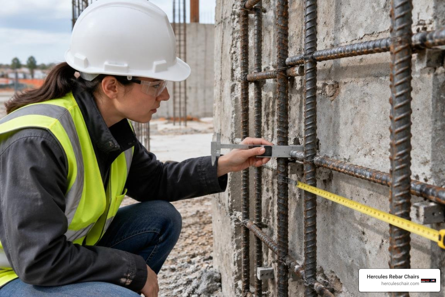
Concrete cover tolerances are non-negotiable in seismic engineering. Meeting the stringent parameters outlined in Chapter 18 Earthquake-Resistant Structures: Arkansas Structural Concrete Code 2019 | UpCodes requires strict adherence to spatial geometry within critical plastic hinge zones. In these high-strain regions, the concrete cover protects the longitudinal reinforcement from premature environmental degradation and helps preserve the structural core under extreme drift demands. Preventing rebar sagging under dynamic loads during the placement of heavy, wet concrete ensures the designed stress distribution remains intact across every structural member.
Concrete Cover Requirements for Slabs, Beams, and Coastal Structures
Concrete cover serves as both a physical barrier against environmental attack and a mechanical boundary layer that transfers stress. Environmental factors dictate the minimum baseline thickness required across different structural components:
- Slabs in Dry Climates: Require a baseline clear cover of 20 mm to maintain fire resistance and structural bond.
- Slabs in Coastal or Humid Environments: Require at least 30 mm of cover to resist aggressive airborne chlorides.
- Beams in Standard Dry Conditions: Require a minimum clear cover depth of 25 mm around stirrups and main longitudinal bars.
- Beams Exposed to Coastal Salt Air: Require 35 mm to 40 mm of dense cover to prevent chloride-induced depassivation.
In coastal zones across the United States—from California to Florida—salt-laden moisture penetrates unsealed or porous concrete. When rebar chairs fail to maintain cover, chlorides reach the steel surface rapidly, initiating an electrochemical reaction that forms iron oxide. Because rust expands up to six times the volume of the original steel, it creates internal radial pressures exceeding the tensile strength of concrete, causing delamination and spalling. Using specialized supports for coastal environments guarantees uniform depth, preventing premature degradation before a seismic event can even test the structure.
Preventing Bar Buckling and Preserving Column Ductility
During strong ground motions, columns in ductile moment frames endure severe axial compression combined with cyclic flexural reversals. A primary failure mode under these conditions is longitudinal rebar buckling, which leads to immediate degradation of axial load capacity.
Stirrup confinement keeps the longitudinal bars from bowing outward. If reinforcement geometry is compromised during the pour—such as when workers step on rebar cages or chairs tip—the effective unsupported length of the main bars increases. Research demonstrates the severe consequences of geometric errors:
- Stirrup Integrity: If a single intermediate stirrup is displaced or removed from a column cage, the load-bearing capacity of that column can plunge by up to 50% because doubling the unsupported length quarters the elastic buckling threshold of the rebar.
- Symmetric Placement: Rebars must remain symmetrically distributed around column perimeters. Even a 10% reduction or localized displacement of reinforcing bars degrades structural capacity in proportion, creating torsional eccentricities under cyclic lateral drift.
Maintaining precise spacing and elevation keeps the rebar cage concentric within the formwork, ensuring every tie and cross-tie engages the longitudinal steel exactly where dynamic structural calculations require.
Engineering Mechanics of Earthquake Resistant Rebar Chairs
Structural chairs must withstand heavy dynamic point loads during construction without crushing, sliding, or puncturing underlying barriers. The table below outlines how different chair designs support structural performance during concrete placement:
| Support Mechanism | Primary Application | Structural Load Distribution | Seismic Stability Consideration |
|---|---|---|---|
| Heavy-Duty Broad Base Polypropylene Chair | Mat foundations, grade slabs, vapor barriers | Disperses heavy multi-layer rebar weight over a wide footprint | Prevents puncturing vapor membranes; resists lateral displacement under heavy pump lines |
| Plastic-Tipped Steel Wire Chair | Architectural slabs, suspended beams, precast panels | Point loads transferred directly through steel legs to firm sub-base | Eliminates exposed carbon steel on exterior concrete surfaces, stopping moisture pathways |
| Indirect S-Shaped & Folded Mesh Spacers | Cantilevered slabs, thin decks, light welded wire mesh | Continuous linear elevation across wide spatial grids | Maintains top negative reinforcement elevation against heavy worker foot traffic |
| J-Pin & Vertical Wall Spacers | Shear walls, boundary elements, vertical columns | Secures steel cages against formwork lateral pressure | Maintains strict perimeter concrete cover during high-frequency vibratory consolidation |
Understanding these structural interactions is fundamental to rebar chair code ensuring stability and compliance on high-consequence jobsites.
Rebar Chair Placement and Load Distribution
During concrete placement, rebar chairs must resist cumulative dead and live loads, including the weight of thick reinforcing mats, wet concrete discharge, pump lines, and installation crews. If chairs lack compressive stiffness or are spaced too far apart, the rebar grid flexes downwards, reducing bottom concrete cover.
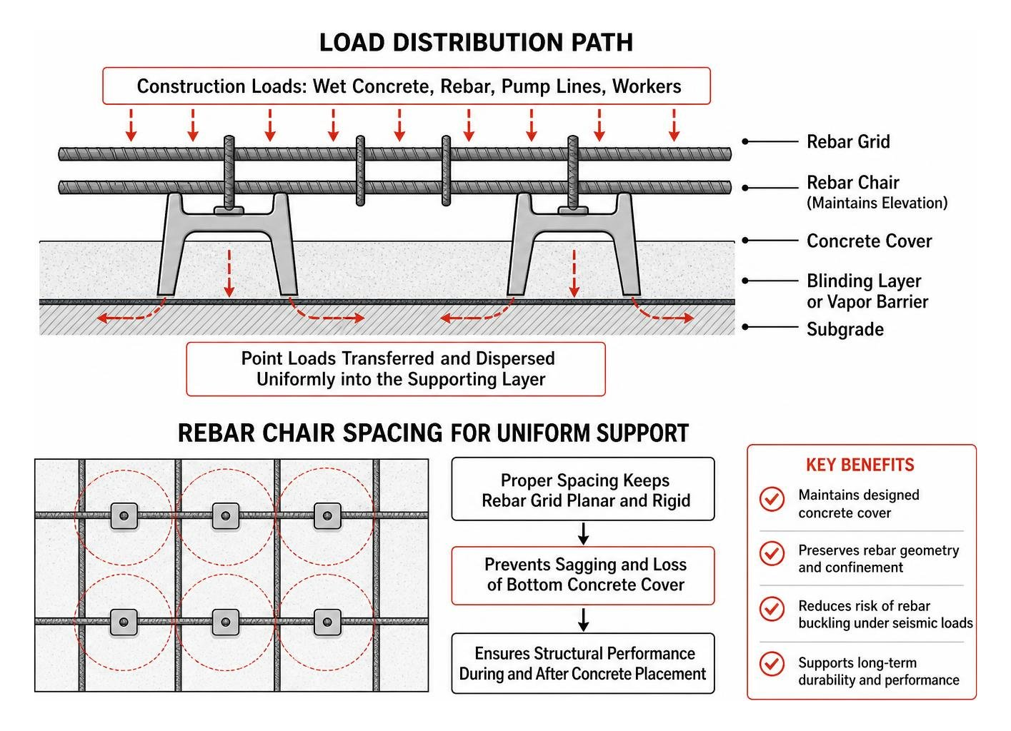
Our practical guide to rebar chair types and sizing highlights the importance of matching the chair’s structural geometry to the expected construction loads. Heavy-gauge reinforcement requires chairs with robust load paths that transfer point forces uniformly into the underlying blinding layer or subgrade without localized settlement.
Material Durability in Seismic Concrete
The use of plain, un-tipped carbon steel spacers is prohibited across modern structural specifications. When bare steel spacers sit directly on formwork, their tips remain exposed at the exterior concrete boundary after stripping. This provides a direct path for moisture, carbon dioxide, and chloride penetration.
As corrosion propagates inward along the spacer leg, it attacks the primary reinforcement, causing internal cracking and bond loss. In seismic regions, this bond degradation prevents the reinforcement from developing its full tensile yield strength during ground motion. To prevent this, structural engineers require high-grade polypropylene chairs or steel chairs equipped with thick, non-corrosive plastic-tipped legs that protect the concrete’s passivation layer.
Seismic Placement and Detailing Across Structural Concrete Elements
Ensuring proper concrete flow and consolidation is essential when building earthquake-resistant elements with dense rebar cages. For standard structural concrete mixes, the clear spacing between adjacent rebar lines must equal at least the maximum aggregate grain dimension plus a 5 mm safety margin. For example, a mix with a 32 mm maximum coarse aggregate requires at least 37 mm of clear clearance between bars.
When working with Self-Compacting Concrete (SCC), where aggregate sizes are generally limited to 16 mm, congestion management remains equally vital. The elevation chairs must provide an unobstructed flow path so aggregate particles do not bridge, which could create internal honeycombing around high-stress beam-column joints.
Selecting Earthquake Resistant Rebar Chairs for Slabs and Beams
Negative moment reinforcement over continuous supports and cantilever balconies requires precise positioning. If top bars in a cantilever slab drop by only 15 mm due to foot traffic during the pour, the slab’s nominal moment capacity can drop by more than 20%, resulting in excessive deflection and cracking under seismic vibrations.
In beam bottoms, maintaining clear cover between 25 mm and 35 mm prevents the stirrup corners from being exposed to early fire damage or environmental degradation. Always inspect your rebar chairs properly to prevent structural slab failure prior to placing concrete, verifying that every snap-lock cradle holds the rebar securely against lateral displacement.
Installing Earthquake Resistant Rebar Chairs in Heavy Foundations
Foundations transfer dynamic overturning moments and shear forces into the ground. Foundation cover depths must reflect site conditions:
- Footings on a Lean Concrete Blinding/Leveling Slab: Require a minimum clear concrete cover of 40 mm.
- Footings Cast Directly on Soil/Subgrade: Require a minimum clear cover of 70 mm to protect against groundwater chemicals and irregular terrain.
In thick mat foundations, specify heavy-duty rebar chairs for chemical and power plant construction that feature wide, flat bases. These wide footprints prevent the chairs from sinking into compacted gravel or puncturing critical poly vapor barriers. Maintain a regular 1.00 m grid spacing to ensure the heavy multi-layered steel mat remains flat and stable during the pour.
Frequently Asked Questions About Seismic Reinforcement Supports
How should rebar chair materials be evaluated for earthquake-resistant concrete construction?
Evaluate rebar chairs based on compressive yield strength, chemical durability, and non-corrosive properties. Avoid bare carbon steel spacers, as exposed metal legs corrode quickly, causing concrete spalling and destroying the rebar-to-concrete bond necessary for seismic ductility. Use heavy-duty, engineered polypropylene chairs or plastic-tipped supports designed to withstand placement impacts without crushing or breaking.
How does concrete cover depth directly influence the seismic performance of a building?
Concrete cover preserves the alkaline passivation layer around reinforcing steel, protecting it from corrosion-induced section loss. During an earthquake, adequate cover confines the inner concrete core within plastic hinge zones, preventing premature cover spalling under high cyclic compression. This confinement allows the structural element to dissipate energy safely through plastic deformation rather than experiencing brittle failure.
What spacing frequency is required for rebar chairs in seismic-rated slabs and foundations?
A spacing frequency of approximately 1.00 m on center is the industry standard for slab and foundation reinforcement grids. In areas with heavy bar bundles, thick foundation mats, or concentrated construction foot traffic, tighten chair spacing to 0.60 m to 0.80 m. This prevents rebar deflection and guarantees that the designed concrete cover is maintained across the entire structure.
Conclusion
Seismic resilience requires balancing structural design with meticulous jobsite execution. Even the most advanced finite element modeling and ductile detailing cannot protect a structure if the rebar shifts or sags before the concrete hardens. Maintaining precise concrete cover with robust, non-corrosive rebar chairs protects primary steel against environmental degradation, limits rebar buckling tendencies, and ensures predictable plastic hinge behavior during severe ground motion.
At Hercules Rebar Chairs (a brand of T.J. Harris Co.), we build high-strength, code-compliant rebar chairs proudly manufactured 100% in the USA. With over 14 million units sold across demanding construction sectors, our distinctive red chairs provide the high load capacities and broad-base stability required to keep your steel where it belongs. Explore our complete selection of high-performance seismic rebar supports to safeguard structural integrity on your next critical concrete pour.