

Code Requirements and Guidelines for Concrete Slab Rebar Spacing
Standard concrete slab rebar spacing is typically 12 to 18 inches on center, with ACI 318 limiting the maximum spacing to 18 inches or 3 to 5 times the slab thickness depending on whether the reinforcement is structural or for temperature and shrinkage crack control. For most residential flatwork, an 18-inch on-center grid is the accepted maximum, while driveways and garage slabs carrying vehicle loads usually use a tighter 12- to 16-inch grid.
When pouring flatwork, concrete offers tremendous compressive strength, but it is notoriously weak in tension. As concrete cures, hydrates, and endures seasonal temperature shifts, it shrinks and pulls against itself. Without steel reinforcement, those tensile stresses lead straight to wide, jagged structural cracks.
Proper rebar placement creates a composite structure where steel carries the tension and concrete shoulders the compressive loads. Building standards like the ACI 318 slab reinforcement standards provide the baseline criteria necessary to control cracking and ensure structural stability. Following guidelines such as ACI CODE-318-25: Building Code for Structural Concrete—Code Requirements and Commentary AC ensures that reinforcement grids meet recognized safety thresholds across residential and commercial pours.
Minimum and Maximum Rebar Spacing in a Concrete Slab Under ACI 318
To design a functional rebar grid, you must balance two structural limits: keeping bars close enough to restrict shrinkage cracks, while leaving enough clear space for concrete aggregate to flow freely without creating rock pockets or voids.
Minimum Clear Spacing: ACI 318 mandates that the clear distance between parallel bars in a layer must not be less than the greatest of:
- 1 inch (25 mm)
- The nominal diameter of the rebar (e.g., 0.5 inches for #4 bar)
- 1.33 times the nominal maximum size of the coarse aggregate If your ready-mix supplier delivers concrete with 3/4-inch aggregate, your minimum clear spacing must be at least 1 inch (3/4 inch × 1.33 = 1 inch). Tighter spacing risks honeycombing because large stones bridge across the bars and block the cement paste.
Maximum Spacing: For crack control and temperature-shrinkage reinforcement in standard slabs-on-ground, ACI code limits the maximum spacing to the lesser of 5 times the slab thickness or 18 inches. For flexural (structural load-bearing) reinforcement, ACI limits spacing to the lesser of 3 times the slab thickness or 18 inches.
To explore these parameters across varied slab depths, review our breakdown on rebar requirements for concrete slabs. In practice, an 18-inch on-center grid serves as the industry standard maximum for residential flatwork.
Concrete Cover and Edge Clearance Standards
Rebar must be completely encased in concrete to prevent moisture penetration, chemical attack, and oxidation. The distance between the outer surface of the rebar and the nearest exterior concrete face is called the concrete cover.
- Concrete cast against and permanently exposed to earth: Minimum 3 inches (75 mm) of clear cover.
- Concrete formed and exposed to earth or weather: Minimum 1.5 inches to 2 inches (40 to 50 mm) for #5 bars and smaller.
- Interior slabs not exposed to weather: Minimum 0.75 inches to 1.5 inches depending on fire ratings and exposure.
Edge distance protects the perimeter of the slab from spalling. Keep perimeter bars 2 to 3 inches away from the forms. In a long-term field study by the National Institute of Standards and Technology (NIST), reinforced assemblies with inadequate cover and irregular bar spacing exhibited corrosion rates up to 40% higher than properly spaced and encased steel over a 10-year period. Rust expands up to six times the original volume of steel, generating internal bursting pressure that destroys concrete from within. Learn more about maintaining correct cover in our comprehensive rebar placement guide.
Lap Splices and Rebar Overlap Rules
Standard rebar comes in stock lengths of 20, 40, or 60 feet. When a slab dimension exceeds stock length, you must overlap two bars side-by-side to transfer tensile stress across the joint.
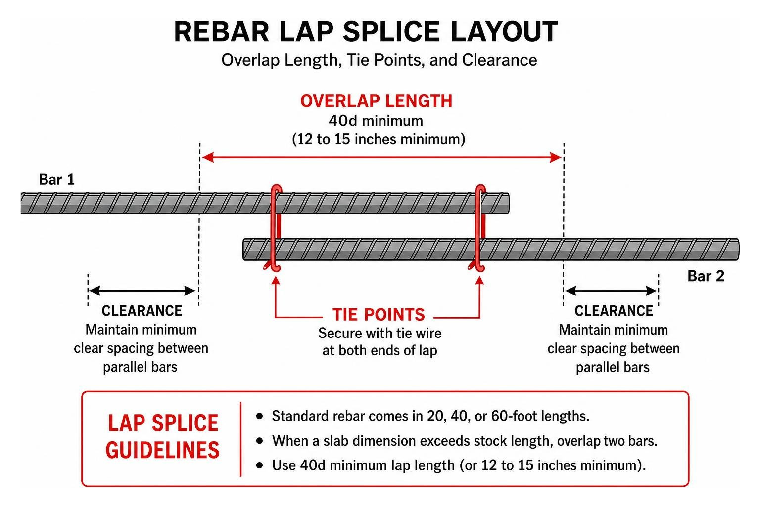
A reliable field rule of thumb for standard tension lap splices in slabs is 40 times the nominal bar diameter (40d), or a minimum of 12 to 15 inches.
- #3 Bar (3/8-inch diameter): 40 × 0.375 in = 15-inch minimum lap.
- #4 Bar (1/2-inch diameter): 40 × 0.500 in = 20-inch minimum lap.
- #5 Bar (5/8-inch diameter): 40 × 0.625 in = 25-inch minimum lap.
Overlap bars in direct contact or separate them horizontally by no more than one-fifth the required lap length (up to 6 inches). Tie lap splices securely with 16-gauge annealed tie wire at the ends and center of the lap to prevent movement when concrete discharges from the pump hose or chute. Always specify deformed steel bars conforming to ASTM A615 (Grade 40 or Grade 60) for reliable yield strength.
Concrete Slab Rebar Spacing and Sizing by Application
Reinforcement requirements depend on expected surface loading, vehicle wheel weights, and slab geometry. The table below summarizes standard residential and light commercial specifications:
| Slab Application | Typical Thickness | Recommended Bar Size | Standard Grid Spacing | Clear Cover (Top / Bottom) |
|---|---|---|---|---|
| Sidewalk / Patio | 4 inches (100 mm) | #3 (3/8 in) or #4 (1/2 in) | 18 in × 18 in | 1.5 in / 2.0 in |
| Residential Driveway | 5 to 6 inches (125–150 mm) | #4 (1/2 in) | 12 in × 12 in to 16 in × 16 in | 1.5 in / 2.0 in |
| Residential Garage | 4 to 6 inches (100–150 mm) | #4 (1/2 in) | 12 in × 12 in to 16 in × 16 in | 1.5 in / 2.0 in |
| Heavy Commercial / Shop | 6 to 8 inches (150–200 mm) | #4 or #5 (5/8 in) | 12 in × 12 in | 2.0 in / 3.0 in |
| Continuous Footings | 8 to 12 inches (200–300 mm) | 2–3 continuous #4 or #5 | Longitudinal runs with ties | 3.0 in bottom & sides |
Determining Rebar Spacing in a Concrete Slab by Thickness
Slab depth determines the volume of concrete undergoing drying shrinkage, which dictates the cross-sectional area of steel required:
- 4-Inch Slabs: Use #3 bar on a 16-to-18-inch grid or #4 bar on an 18-inch grid. With only 4 inches of total depth, precise vertical positioning is essential to maintain at least 1 inch of concrete above and below the steel.
- 5-to-6-Inch Slabs: Standard for driveways and structural floors. Deploy #4 bar spaced at 12 to 16 inches center-to-center.
- 8-Inch Slabs: Heavy-duty industrial pours support massive dead and live loads. Use #5 bar placed on a 12-inch grid. Slabs 8 inches or thicker frequently require a double mat of steel (top and bottom layers) supported by vertical standoffs.
Garages, Driveways, and Heavy-Load Slabs
Slabs that carry vehicular traffic face dynamic, repetitive point loads. A garage floor supporting a heavy pickup truck, an RV, or a car lift experiences high flexural stresses directly under the tire contact patches.
For heavy municipal or multi-level garages, consult detailed parking garage concrete slab specifications where exposure class C2 (chloride and deicing salts) requires minimum 4,000 to 5,000 PSI mixes and tight 12-inch on-center grids with #5 rebar.
Continuous Footers, Cutouts, and Control Joints
Foundations and discontinuous slab sections require specialized reinforcement strategies:
- Continuous Trench Footings: Footers carry wall loads down to stable subgrade. Rather than a cross-hatch grid, footers typically utilize two or three continuous runs of #4 or #5 rebar running along the trench, elevated 3 inches off the ground and tied at splices.
- Slab Cutouts and Openings: Plumbing rough-ins, sumps, and structural columns create stress concentrations at their corners. Add diagonal “trimmer bars” (two 4-foot lengths of #4 rebar placed diagonally across each 90-degree corner) 2 inches back from the cutout to prevent re-entrant corner cracking.
- Control Joints: Control joints create weakened planes so concrete cracks along clean, predetermined lines. When saw-cutting joints (typically to a depth of one-quarter of the slab thickness), ensure the rebar is placed low enough that the saw blade does not sever the steel, or terminate rebar 2 inches away from un-doweled contraction joints to allow the joint to activate properly.
Rebar vs. Welded Wire Mesh Reinforcement
Builders often weigh traditional rebar against Welded Wire Reinforcement (WWR/mesh):
While welded wire mesh can work for thin walkways, light sheets easily get trampled to the dirt during the pour. When using wire sheets, discover how to properly space wire mesh chairs to prevent the mesh from resting flat on the vapor barrier.
How to Calculate Rebar Spacing and Total Quantity for Slabs
Accurately calculating materials ensures you do not run short during the pour or overspend on surplus steel. If you prefer automated numbers, read our guide on calculating rebar for a concrete slab.
Step-by-Step Rebar Quantity Calculation Formula
Follow this straightforward mathematical process to calculate your grid:
- Subtract Edge Clearances: Deduct the required edge clear cover (e.g., 3 inches on each side = 6 inches total) from both the length and width of the slab to find the active reinforcement grid dimensions.
- Grid Length = Slab Length – (2 × Edge Cover)
- Grid Width = Slab Width – (2 × Edge Cover)
- Calculate the Number of Grid Spaces: Divide the grid dimension by your chosen spacing (e.g., 18 inches / 1.5 feet), then round up to the next whole number.
- Number of Spaces along Length = Grid Length / Spacing (rounded up)
- Number of Spaces along Width = Grid Width / Spacing (rounded up)
- Determine Bar Counts Per Direction: Add 1 to the number of spaces to account for the closing edge bar.
- Number of Transverse Bars (running across width) = Spaces along Length + 1
- Number of Longitudinal Bars (running along length) = Spaces along Width + 1
- Calculate Total Linear Footage:
- Total Feet = (Transverse Bars × Grid Width) + (Longitudinal Bars × Grid Length)
Worked Example: 20-Foot × 20-Foot Garage Slab
- Slab Dimensions: 20 ft × 20 ft
- Rebar Grid: #4 bar on an 18-inch (1.5-foot) grid
- Edge Cover: 3 inches (0.25 ft) per side
- Grid Dimensions: 20 – 0.5 = 19.5 ft by 19.5 ft
- Spaces per Side: 19.5 ft / 1.5 ft = 13 spaces
- Bars per Direction: 13 + 1 = 14 bars in each direction (28 bars total)
- Base Linear Footage: 28 bars × 19.5 ft = 546 linear feet
Accounting for Lap Splices, Grids, and Waste Allowances
Because standard rebar comes in 20-foot sticks, continuous runs over 19.5 feet in a real-world slab require splices or cutting trimmed ends. Always add a 10% allowance for lap splices, cuts, and corner reinforcement.
- Total Linear Feet with 10% Allowance = 546 ft × 1.10 = 600.6 linear feet.
- Number of 20-Foot Stock Bars Needed = 601 ft / 20 ft per bar = 30.05 (order 31 bars).
- Total Weight (#4 rebar weighs 0.668 lbs/ft) = 601 ft × 0.668 lbs/ft = 401.5 lbs of steel.
Best Practices for Positioning, Soil Subgrade, and Rebar Support
Even a perfectly calculated rebar grid will fail if the soil base settles or if the steel sinks to the dirt. Master these jobsite standards alongside our guide on how to place rebar like a pro.
Subgrade Compaction and Soil Conditions
Concrete is only as solid as the ground beneath it. Weak soils cause differential settlement, causing the slab to bridge unsupported voids and crack under load.
- Excavate Organic Soil: Remove all topsoil, sod, and clay down to firm inorganic subgrade.
- Install Crushed Stone Subbase: Place 4 to 6 inches of crushed aggregate (such as 3/4-inch minus crushed stone).
- Compact in 3-Inch Lifts: Run a mechanical plate compactor over the stone base in maximum 3-inch lifts to reach 95% standard Proctor compaction.
- Vapor Barrier: For enclosed slabs (garages, basements, shops), lay a minimum 10-mil to 15-mil poly vapor barrier over the stone base to block ground moisture. Seal all seams with vapor-tape.
Vertical Positioning: Placing Rebar at Mid-Depth vs. Bottom
When a vehicle or heavy load presses down on a slab-on-ground, the slab flexes downward like a shallow dish. This puts the bottom third of the concrete under direct tension, while the top surface is in compression.
- For slabs 4 to 5 inches thick: Place the rebar grid at the center (mid-depth) or slightly below center (2 inches off the bottom subgrade).
- For slabs 6 inches or thicker: Position rebar in the lower third of the slab cross-section (approximately 2 inches clear above the subgrade) where tensile stresses peak.
- Maintain at least 1.5 to 2 inches of concrete cover over the top of the rebar to prevent surface cracking. For complete spacing steps, check out using concrete slab spacers.
Using Rebar Chairs and Spacers to Prevent Sagging
The old jobsite myth of “hooking and pulling” rebar up with a rake while pouring does not work. Once laborers step forward to screed, the steel gets stamped right back into the dirt. Rebar must be mechanically supported prior to the pour.

At Hercules Rebar Chairs (T.J. Harris Co.), we manufacture heavy-duty, purpose-built concrete supports designed to withstand jobsite abuse. As America’s #1 rebar chair supplier with over 14 million units sold across all 50 states, our signature red chairs save contractors valuable setup time, eliminate re-work, and ensure 100% code-compliant concrete cover.
- Chair Spacing Intervals: Space rebar chairs every 3 to 4 feet along the grid intersections. Heavy-gauge #5 bar can span up to 4 feet between chairs; lighter #3 bar requires support every 2.5 to 3 feet to prevent sag.
- Stable Base: On sand, gravel, or vapor barriers, select wide-base plastic chairs that will not puncture the moisture barrier or sink into the stone base.
- For product styles and load ratings, consult our guide to rebar chairs and sizing and our rebar slab support complete guide.
Common Installation Mistakes to Avoid
- Laying Steel Directly on Ground: Placing rebar on dirt or gravel leaves zero bottom cover, exposing steel to water and causing immediate corrosion.
- Bricking with Porous Pavers: Using porous landscape pavers or clay bricks as supports introduces foreign, moisture-wicking materials that fracture concrete under load. Always use engineered plastic rebar chairs.
- Severing Bars at Saw Joints: Cutting contraction joints too deep can sever the rebar grid, eliminating structural tie capacity across adjacent slab panels.
- Skipping Lap Splice Ties: Failing to tie overlapping bars allows them to shift apart under concrete chute pressure, creating unreinforced seams.
- Zero Edge Clearance: Running rebar all the way to the wooden form boards exposes the bar ends to outdoor air once forms are stripped, causing rust streaks.
Frequently Asked Questions About Concrete Slab Reinforcement
Do I need rebar in a 4-inch thick concrete slab?
For non-structural, light pedestrian flatwork like a backyard walkway or small patio built on stable, compacted gravel, a 4-inch slab can perform adequately without heavy rebar, relying on welded wire mesh. However, if that 4-inch slab will support vehicular traffic, shed equipment, or hot tubs—or if you live in severe freeze-thaw zones—installing #3 or #4 rebar on an 18-inch grid is strongly recommended to prevent settlement cracking.
How far should rebar be placed from control joints?
Keep rebar at least 2 inches clear vertically below the planned cut depth of the control joint. If your control joints are saw-cut 1.25 inches deep in a 5-inch slab, your rebar should sit on chairs holding it 2 inches off the subgrade (giving 1.75 inches of clearance above the steel). If specifying un-bonded expansion joints or doweled joints, terminate standard grid rebar 2 to 3 inches away from the joint line.
How does rebar spacing differ for slab-on-grade vs. elevated decks?
A slab-on-grade relies on continuous ground support across its entire footprint, meaning rebar primarily serves as temperature-shrinkage crack control placed on an 18-inch single grid. An elevated structural deck spans unsupported space between beams or columns. Elevated decks endure major two-way bending, requiring engineered top-and-bottom reinforcement mats spaced tightly (typically 6 to 12 inches on center) with heavy bar sizes (#5 through #8) calculated by a structural engineer.
Conclusion
Laying out a durable, code-compliant concrete slab comes down to three structural rules: setting the correct grid spacing for your load (12 to 16 inches for vehicles, 18 inches for standard residential flatwork), providing proper concrete cover, and locking the steel at the right height using reliable rebar chairs.
Never let your steel grid sink into the mud. Take the guesswork out of your next pour by using quality red supports from Hercules Rebar Chairs (T.J. Harris Co.)—trusted across America with more than 14 million chairs sold. For deeper planning calculations, check out our guide on how to calculate rebar for a slab the right way and build your next slab to last for generations.