

Continuous Supports: Choosing the Right System for the Job
Continuous supports are systems that provide ongoing support across a length, multiple points, or an uninterrupted period. For concrete work, this often means continuous rebar supports, such as wire spacers or slab bolsters, that hold reinforcing steel at the specified elevation and help maintain concrete cover during a pour.
The same phrase also appears in other fields, so context matters:
- In structural engineering, a continuous beam spans across more than two supports. It redistributes loads and generally has lower deflection and lower positive bending moments than a comparable simple span.
- In concrete reinforcement, continuous support products help keep rebar from sagging, shifting, or losing its required position.
- In 3D printing, organic supports use branching forms rather than dense grid structures, reducing material use and making removal easier.
- In business writing, use continued support when thanking a customer, donor, or partner for ongoing patronage. Use continuous support for uninterrupted service, such as 24/7 technical assistance.
For contractors, the practical goal is straightforward: choose a durable support system that maintains reinforcement location, meets the project specifications, and stays stable while crews place concrete.
I am Jordan Harris, a Tennessee Professional Engineer with experience in large concrete and steel projects, product development, and manufacturing. At Hercules Rebar Chairs, I apply that structural and jobsite perspective to continuous supports that help contractors place reinforcement accurately and efficiently.
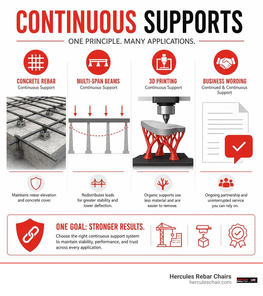
Understanding Continuous Supports Across Structural, Manufacturing, and Linguistic Contexts
The term “support” changes meaning depending on whether you are talking to a civil engineer, a software technician, a manufacturing technician, or an executive drafting an annual report. At its core, any support system provides stability, equilibrium, and resistance against unwanted displacement.
In public administration and healthcare, state programs like Continuous Residential Supports (CRS) – CT.gov provide 24-hour daily operational care for individuals needing uninterrupted assistance. Similarly, in structural design, civil infrastructure, and additive manufacturing, continuity ensures that forces flow smoothly without abrupt structural failure.
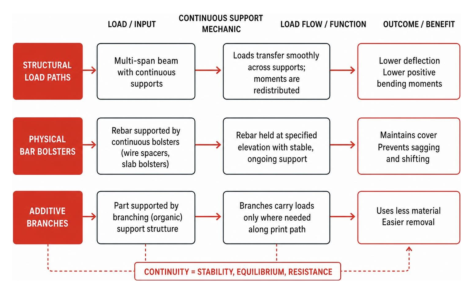
Continuous Support vs Continued Support in Professional Correspondence
A common point of confusion in business and donor correspondence is the difference between “continuous support” and “continued support.” While they sound nearly identical, their grammatical implications differ significantly:
- Continuous Support: Refers to an unbroken, non-stop duration of action or operation without interruption. It is typically used for mechanical operations, 24/7 server monitoring, and technical service level agreements (SLAs). For example: “Our IT department provides continuous support throughout the server migration.”
- Continued Support: Refers to recurring, voluntary actions maintained over a sustained period, even if separated by discrete intervals. It is the standard, polite phrasing for thanking clients, donors, or stakeholders. For example: “Thank you for your continued support of our charitable mission.”
When drafting thank-you notes, client emails, or annual donor reviews, opt for “continued support.” Using “continuous support” in donor correspondence implies that the donor never pauses, which sounds unnatural. Save “continuous” for uninterrupted operational baselines.
Overview of Physical and Computational Support Systems
In the physical world of construction, continuous supports provide uninterrupted linear stability along mats and cages of reinforcing steel. Rather than placing individual, isolated blocks every few feet, continuous supports carry entire grids uniformly, preventing mid-span sag and maintaining critical cover.
Computationally, whether modeling structural boundary conditions or educational governance under Continuous Improvement and Support Systems in California, support systems rely on defined constraints. In finite element analysis (FEA), boundary nodes are assigned specific translational and rotational degrees of freedom to reflect real-world fixity accurately.
Structural Engineering: Continuous Beams and Reinforcement Systems
In structural mechanics, a continuous beam is defined as a member that rests on three or more supports. Unlike a single-span simply supported beam—which can be solved directly using the three standard equations of static equilibrium ($\sum Fx = 0$, $\sum Fy = 0$, $\sum M = 0$)—a continuous beam is statically indeterminate.
As detailed in structural resources like Continuous Beams Explained {2026} – Structural Basics, calculating these systems requires compatibility equations, moment distribution methods, or finite element analysis.
Static Systems and Bending Moment Redistribution in Continuous Beams
When a continuous beam spans over intermediate supports, the structural behavior changes dramatically compared to a simply supported beam:
- Deflection Reduction: The intermediate supports restrain rotational freedom across spans, stiffening the overall system and significantly cutting deflections.
- Moment Redistribution: Instead of concentrating all flexural stress as positive (sagging) bending moment at the bottom of the mid-span, continuous spans redistribute forces. Negative (hogging) bending moments develop over the top of the intermediate supports.
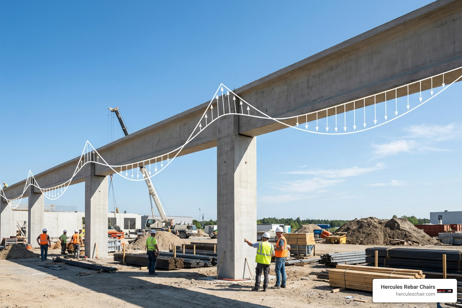
Consider standard uniform distributed loading ($q$) across continuous spans of equal length ($l$):
- Two-Span Continuous Beam: Under full uniform distributed load across both spans, the maximum positive bending moment drops to $\frac{49}{512}ql^2 \approx 0.0957 ql^2$ (with single-span loading conditions generating peak positive moments of $\frac{49}{512}ql^2$ and negative moments at the central support reaching $-\frac{1}{16}ql^2 = -0.0625 ql^2$).
- Three-Span Continuous Beam: With a UDL applied across two neighboring spans, the maximum positive bending moment is approximately $0.0735 ql^2$, with peak negative bending moment over intermediate support $B$ reaching $-0.117 ql^2$.
- Four-Span Continuous Beam: Under full uniform load on all spans, the maximum positive bending moment is restricted to $0.077 ql^2$, while interior supports $B$ and $D$ absorb peak negative moments of $-0.107 ql^2$.
Because peak positive moments are reduced compared to simple spans ($M = \frac{ql^2}{8} = 0.125 ql^2$), designers can specify smaller cross-sections and optimize reinforcing steel.
Implementing Continuous Supports in Reinforced Concrete Slabs
In concrete construction, the theoretical continuity modeled in engineering drawings depends on physical bar supports on the jobsite. Maintaining specified concrete cover is essential to protect rebar from corrosion, fire damage, and flexural failure. When placing bottom rebar mats or post-tensioned tendons across long runs, learning how to use galvanized rebar chairs and continuous wire spacers like a pro helps prevent rebar displacement during the pour.
On heavy civil and commercial slabs, single point chairs can sometimes shift or punch through soft subgrades if not sized correctly. Using heavy-duty continuous slab bolsters and wide-base chairs provides uninterrupted support beneath bottom mats. Make sure don’t let your rebar sag with these support tools becomes your crew’s guiding rule, ensuring steel remains at its designed elevation when workers walk the deck.
Designing and Modeling Support Fixity in Structural Software
In structural engineering software such as Tekla Structural Designer, modeling how elements connect to supports dictates load paths. Engineers configure boundary conditions using the guides found in Create supports | Trimble User Assistance.
Structural software calculates fixity using translational ($Fx, Fy, Fz$) and rotational ($Mx, My, Mz$) degrees of freedom:
- Fully Fixed: All six degrees of freedom are fully restrained.
- Pinned: Translational movement is fully restrained, while rotational axes remain free.
- Spring Supports: Flexible boundary conditions that model soil-structure interaction, ground settlement, or elastomeric bearing pads by defining linear ($kN/mm$) or non-linear stiffness curves.
- Nominally Pinned / Nominally Fixed Column Bases: Set rotational stiffness based on column flexural rigidity using the equation:
$$\text{Stiffness} = \alpha \times \left(\frac{4EI}{L}\right)$$
Where $\alpha = 0.10$ (10%) for nominally pinned bases and $\alpha = 1.00$ (100%) for nominally fixed bases.
Structural Mechanics: Continuous Supports vs Simply Supported Systems
Selecting between a series of simply supported single spans and an unbroken continuous system involves key engineering trade-offs.
| Performance Metric | Simply Supported Beam (Single Span) | Continuous Beam (Multi-Span) |
|---|---|---|
| Static Determinacy | Statically Determinate (3 equilibrium equations) | Statically Indeterminate (FEA / Moment distribution) |
| Mid-span Positive Moment | High ($M_{max} = \frac{wl^2}{8} = 0.125 wl^2$) | Low (typically $0.070 wl^2$ to $0.095 wl^2$) |
| Support Negative Moment | Zero at ends ($M = 0$) | Significant hogging moments at intermediate supports |
| Maximum Deflection | High ($\delta = \frac{5wl^4}{384EI}$) | Low (often reduced by 40% to 60% relative to simple spans) |
| Joint & Bearing Hardware | Requires expansion joints and double bearings at piers | Minimal expansion joints; continuous deck pours |
| Foundation Settlement Risk | Tolerant to differential settlement | Induces secondary internal moments if supports settle |
For slabs and elevated decks, choosing the right bar supports is just as vital as the analysis. Reviewing the ultimate guide to rebar chairs: types, uses, and sizing for concrete slabs ensures you match your structural layout to field-ready hardware.
Flexural Efficiency and Deflection Control
Continuous multi-span systems save material. By pulling flexural tension into the top of the slab over interior supports, continuous systems balance peak sagging moments at mid-span. This lower moment allows engineers to specify shallower beam depths and thinner slabs without violating serviceability deflection limits.
Understanding the various support systems available—from individual point supports to linear profiles—is outlined in from dobies to double mats: a comprehensive look at rebar chair types.
Detailing Requirements at Interior Supports
Because continuous beams develop high negative moments over intermediate supports, reinforcement detailing is critical:
- Top Reinforcement Placement: High flexural tension occurs along the top face over interior piers and framing beams. Top steel must extend 20% to 30% into the adjacent spans to anchor past inflection points.
- Torsional Stiffness Checks: Secondary beams framed into girders transfer torsion. If the supporting girder is torsionally stiff, it attracts negative moment, requiring nominal top rebar even if designed as simply supported.
- Shear and Hanging Stirrups: Peak vertical shear occurs adjacent to interior supports. Tightly spaced stirrups and hanging ties are essential to transfer loads safely through the support junction, as detailed in our rebar slab support complete guide.
Advanced Additive Manufacturing: Organic Continuous Supports in 3D Printing
In 3D printing (additive manufacturing), the concept of continuous supports takes on an entirely different, geometric form. Traditional 2D slicers generated dense, vertical grid scaffolding beneath overhangs, which consumed excessive filament, increased print times, and left heavy scars on part surfaces.

Modern slicers utilize Organic Supports (an advanced evolution of tree supports), documented thoroughly in the Organic Supports | Prusa Knowledge Base. These structures grow like branching limbs, curving around model features to support overhangs without adhering to critical vertical side walls.
Optimizing Branch Angles and Slicer Parameters
Organic supports rely on smooth, circular cross-sections oriented perpendicular to the branch axis, reinforced by automatic double perimeter walls for lateral stability.
Key slicer settings include:
- Maximum Branch Angle: Sets the maximum allowable angle a branch can lean away from the vertical axis. Lower angles (e.g., 40°–45°) produce more vertical, rigid trunks that resist buckling. Higher angles allow branches to reach around complex geometry.
- Preferred Branch Angle: The default target angle used by the slicing algorithm when routing around open space.
- Branch Diameter & Diameter Angle: Controls trunk thickness and tapering from the build plate up to the contact interface, providing rigidity at the base and delicate tips at the model contact point.
- Tip Diameter & Interface Layers: Controls the contact point area. Well-tuned interface gaps allow organic supports to snap away cleanly by hand without leaving scars on the finished part.
Frequently Asked Questions About Continuous Support Systems
What is the difference between continuous support and continued support?
“Continuous support” describes an unbroken, non-stop operational service (such as 24/7 web hosting or continuous structural spans). “Continued support” refers to ongoing, voluntary patronage or recurring assistance over time, making it the proper phrase for client and donor communications.
Why are continuous beams structurally superior to simply supported beams?
Continuous beams span over multiple intermediate supports, which redistributes internal forces and creates negative moments over supports. This reduces peak positive mid-span bending moments and lowers deflection, allowing for longer clear spans, shallower beam cross-sections, and lower material costs.
How do organic continuous supports benefit additive manufacturing?
Organic continuous supports branch upward efficiently using circular cross-sections and double perimeter walls. They bypass lower model details, use significantly less filament than traditional grid blocks, shorten print times, and detach cleanly without surface scarring.
Conclusion
Whether you are distributing structural bending moments across multi-span highway bridges, configuring organic branches in slicing software, or maintaining reinforcement elevations on the jobsite, continuous supports are fundamental to structural performance.
At Hercules Rebar Chairs (T.J. Harris Co.), we build that same reliability into every rebar chair and support we manufacture. As America’s #1 choice with over 14 million units sold across all 50 states, our signature red chairs and continuous support systems are engineered to save contractors time, cut labor costs, and ensure strict code compliance on every pour.
For a deeper dive into optimizing your long-span concrete reinforcement, read the long span solution: understanding continuous rebar supports and ensure your steel remains secure from the first pour to the final cure.