

Concrete Slab Support Starts With the Right Load Path
Effective concrete slab support means matching the slab, base, reinforcement, and expected loads to the job. Start by deciding whether the slab bears on prepared soil or spans between beams, walls, or columns. Then verify soil conditions or structural supports, specify adequate thickness and reinforcement, and keep the steel at the correct elevation during the pour.
A slab-on-grade depends on uniform, compacted subgrade to prevent settlement and cracking. A suspended slab depends on its span, thickness, concrete strength, reinforcement, and support layout to resist bending, shear, and deflection. In both systems, concentrated loads from vehicles, safes, racks, or machinery need special attention because they can overload a small area even when the overall slab seems adequate.
For contractors, the practical goal is simple: create a stable base, place reinforcement where the design requires it, maintain concrete cover, and plan for movement, joints, and exposure before concrete arrives. Reliable rebar chairs help prevent reinforcement from sagging onto the base, where it cannot perform as intended.
I am Jordan Harris, a Tennessee Professional Engineer with civil and structural engineering degrees and five years of experience on large concrete and steel projects. Today, I apply that background to practical concrete slab support solutions and rebar-support products built for dependable, efficient pours.
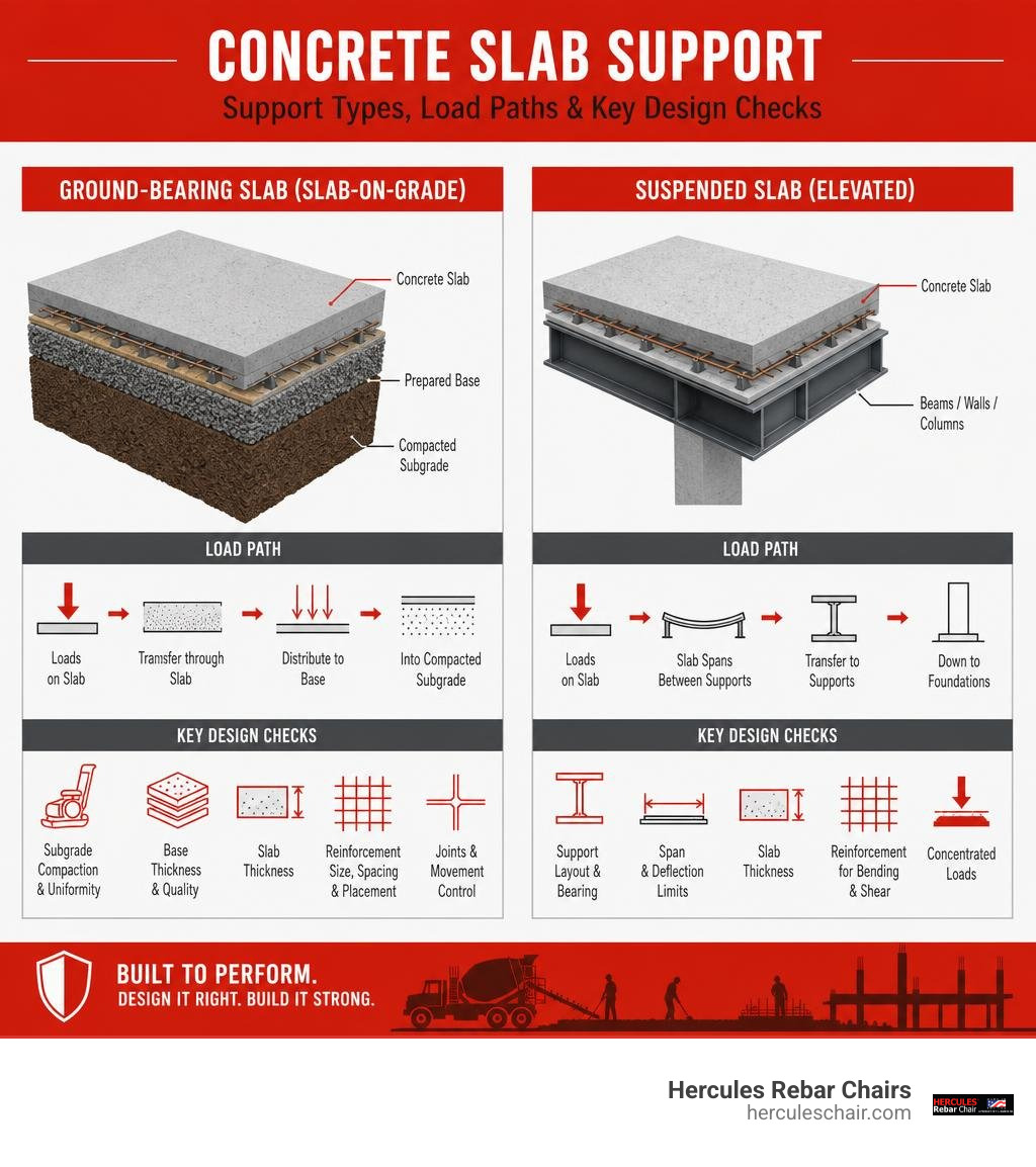
Core Types of Concrete Slab Support and Structural Systems
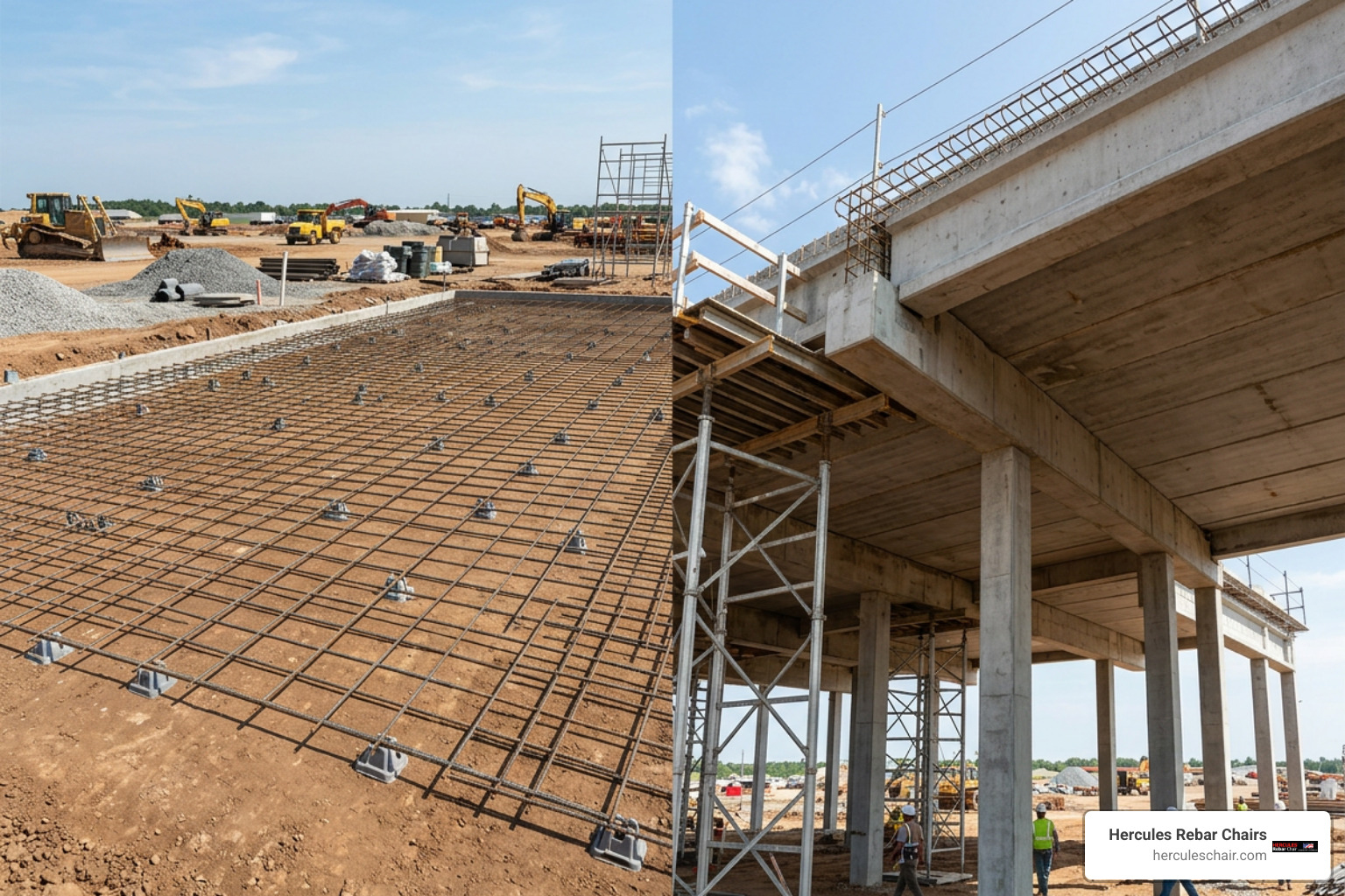
Every concrete floor falls into one of several structural classifications. Understanding how gravity loads and environmental forces transfer through a slab into the earth determines the reinforcement layout, structural depth, and construction sequence required on-site.
Subgrade and Ground-Bearing Concrete Slab Support
A ground-bearing slab (commonly called a slab-on-grade) transfers 100% of its dead and live loads directly to the underlying soil. Because concrete possesses immense compressive strength but weak tensile capacity, any uneven settlement in the subgrade produces flexural tension that causes unreinforced surfaces to crack.
Subgrade preparation requires uniform compaction. Granular fill should be placed in lifts (typically up to 800 mm for clean sand or 400 mm for cohesive soils) and compacted to achieve a predictable modulus of subgrade reaction. Over this prepared base, contractors install a vapor barrier (damp-proof membrane) to halt moisture migration.
In some cases, unreinforced mud slabs (also called “blinding layers” or “rat slabs”), ranging from 50 to 150 mm thick, are poured without steel. A mud slab establishes a level, clean working platform and prevents point loads from heavy equipment or crew foot traffic from disturbing the subgrade. More importantly, understanding why your slab needs rebar chair supports highlights that a stable base stops reinforcement chairs from punching into soft ground, ensuring steel remains locked in the upper tension zone where it belongs.
Suspended Concrete Slab Support and Load Distribution
Unlike ground-bearing assemblies, suspended concrete slabs span between elevated structural members—such as poured-in-place concrete beams, structural steel framing, masonry load-bearing walls, or reinforced concrete columns. They do not rely on soil contact beneath the span.
Suspended slabs must resist significant flexural bending moments and deflection under service loads. Standard residential apartment floors are engineered to support a minimum uniform live load of 40 to 50 pounds per square foot (psf) per building codes.
Concentrated point loads present a different design challenge. For example, a 4-inch suspended slab can typically accommodate a concentrated load of up to 2,000 lbs applied over a 3 ft × 3 ft area. If an owner places a heavy commercial safe or machinery weighing 950 lbs on a compact footprint (such as 24 in × 30 in), the concentrated load accounts for over 50% of that design zone. Spreading point loads across the span using steel plates or structural sub-framing prevents local punching shear failures. For detailed analysis and design of these elevated floors, structural engineers reference the Two-Way Concrete Floor Slab with Beams System Analysis and Design (ACI 318-14) guidelines.
Waffle, Ribbed, and Void-Former Slab Systems
When large column-free spans or poor surface soils make solid thick slabs uneconomical, ribbed and waffle systems provide an ideal structural alternative. These configurations use geometric voids to eliminate non-structural concrete from the tension zone below the neutral axis, cutting structural dead weight while maintaining overall flexural depth.

One widespread approach is the waffle-raft foundation system, detailed in documents like the TECHNICAL MANUAL for engineered pod foundations. These systems utilize modular expanded polystyrene (EPS) pods or recycled plastic domes (such as Qpod systems) measuring 1100 mm × 1100 mm and 220 to 300 mm deep.
Arranged at 1200 mm center-to-center spacings, these pods form a grid of 100 mm wide internal concrete ribs topped by a continuous reinforced concrete layer. This creates an interconnected T-beam grid that resists foundation racking on expansive soils while dampening mechanical vibrations. These systems are commonly engineered for residential dead loads of 0.5 to 2.2 kPa, uniform live loads of up to 3 kPa, point loads of 2.7 kN, and maximum vehicle point loads of 25 kN (approx. 5,600 lbs).
Structural Design and Reinforcement Placement Methods

Reinforcement steel is ineffective if it shifts out of place during the pour. Maintaining proper vertical placement ensures the internal moment arm ($d$) matches structural engineering calculations.
One-Way vs. Two-Way Slab Load Paths and Moments
The load distribution mechanism in a suspended slab depends primarily on its aspect ratio (the ratio of long span to short span):
- One-Way Slabs (Aspect Ratio $\ge$ 2:1): The slab bends primarily across its shorter span. Gravity loads transfer in a single direction to the parallel supporting beams or walls. Flexural steel runs perpendicular to the supports, while secondary transverse steel provides shrinkage and temperature crack control.
- Two-Way Slabs (Aspect Ratio < 2:1): The slab deflects in a dish-shaped curve, transferring loads in two perpendicular directions toward all four perimeter beams or directly into column points.
When analyzing two-way systems using the Equivalent Frame Method (EFM), engineers divide the slab into column strips (which carry higher moments and at least 75% of the negative bending moment) and middle strips. For flat-plate systems without beams, column heads are susceptible to punching shear stresses. Designers incorporate drop panels or localized shear studs to increase the effective shear perimeter around columns.
Internal Reinforcement Elevation and Cover Standards
Steel must sit at precise depths within the slab to develop its rated capacity and resist corrosion. In suspended slabs, bottom-mat steel handles positive mid-span moments, while top-mat steel resists negative moments over support columns and beams.
When rebar settles toward the bottom of the formwork, the structural moment capacity drops dramatically. Contractors eliminate bar sag by preventing reinforcement sagging with heavy duty rebar bolsters along primary steel lines.
Furthermore, checking the selection of rebar chairs and spacers ensures the correct chair height is selected for the specified aggregate size and rebar diameter, providing the required 1.5 to 2 inches of clear concrete cover against moisture-induced rebar oxidation.
Sizing Slab Thickness: 4-Inch Residential vs. 6-Inch Heavy-Duty Slabs
A 4-inch (100 mm) slab using 3,000 to 4,000 PSI compressive strength concrete is standard for residential living rooms, hallways, and light foot-traffic zones. However, thin slabs lack the structural capacity for heavy vehicle storage, machine shops, or high concentrated loads.
Upgrading to a 6-inch (150 mm) profile with 4,000+ PSI mix designs increases shear resistance and flexural capacity by more than 100%. For workshop environments and vehicle bays, contractors should specify heavy-duty garage slab rebar supports to support double mats of #4 or #5 rebar without displacement during pumping.
| Performance Attribute | 4-Inch Residential Slab | 6-Inch Heavy-Duty Industrial Slab |
|---|---|---|
| Typical Compressive Strength | 3,000 – 3,500 PSI (20 MPa) | 4,000 – 5,000 PSI (28 – 35 MPa) |
| Primary Reinforcement | Welded wire reinforcement or #3 rebar @ 18″ OC | #4 or #5 rebar @ 12″ OC (Single or Double Mat) |
| Uniform Live Load Rating | 40 – 50 psf (2.0 – 2.4 kPa) | 100 – 250+ psf (4.8 – 12.0+ kPa) |
| Concentrated Point Load Limit | Up to 2,000 lbs (over 3’x3′ area) | 5,000 – 10,000+ lbs |
| Primary Application | Living areas, basements, patios | Garages, workshops, RV pads, warehouses |
Geotechnical and Environmental Support Considerations
A concrete slab performs only as well as the geotechnical foundation beneath it. Compressible, expansive, or saturated soils require specialized ground engineering to avoid structural failure.
Soil Bearing Capacity and Subgrade Improvement
When native soils exhibit poor bearing capacity (such as soft clays, loose silts, or organic layers), standard slab-on-grade foundations risk differential settlement. Excavating deep subgrades is often costly, making intermediate ground improvement practical.
Rammed Aggregate Pier (RAP) elements offer a reliable solution. By compacting crushed stone into drilled cavities, RAPs create high-stiffness columns that reinforce the surrounding matrix soil. As outlined in the No. 10 technical bulletin on floor slab support, RAP piers provide a spring stiffness (often around 150 pci) substantially higher than native soils (5 to 30 pci).
This stiffness differential controls total settlement to under 25 mm over a 50-year service life. Because the piers introduce non-uniform support conditions across the slab bottom, finite element modeling using software like the spSlab-spBeam-v10.00-Technical-Manual is recommended to analyze localized flexural moments and position slab joints directly over pier centers.
Thermal Performance, Insulation, and Lateral Stability
Concrete features a high thermal conductivity, typically ranging between 0.8 and 2.0 W·m⁻¹·K⁻¹. Uninsulated slabs act as thermal bridges, losing substantial interior heat to the ground. Installing high-density expanded polystyrene (EPS) or extruded polystyrene (XPS) panels directly beneath the slab isolates its thermal mass, helping regulate indoor temperatures during seasonal shifts.
For lateral resistance against wind and seismic events, the interface between the concrete base and compacted subgrade relies on friction, generally calculated using a friction coefficient ($\mu$) of 0.6. In higher seismic zones, reinforced concrete shear keys and perimeter grade beams cast into stable soil layers provide mechanical anchorage against lateral sliding.
Remediation and Strengthening of Compromised Slabs
Renovations, tenant fit-outs, or utility installations often cut through existing suspended slabs, weakening the original structural reinforcement.
Repair Strategies for Slabs Damaged by Chase Cuts
When plumbing or HVAC contractors cut a utility chase through a suspended slab, they sever the tension reinforcement. For example, a 5-inch suspended slab spanning 12 feet with #3 bars at 12 inches on-center will become under-reinforced and exceed steel yield stress if mid-span continuity is lost.
Engineering repair strategies include:
- Mid-Span Structural Beams: Installing a structural steel I-beam or precast concrete lintel beneath the severed span, supported on new columns or structural walls, effectively bisecting the span and reducing bending moments.
- High-Strength Non-Shrink Grouting: Packing the utility void around pipes with non-shrink structural grout to re-establish compressive load transfer.
- Fiber-Reinforced Polymer (FRP): Applying externally bonded carbon-fiber sheets to the slab underside per ACI 440 guidelines. While FRP adds significant flexural tension capacity, it provides minimal deflection recovery, requiring the slab to be jacked level prior to bonding.
- Bolted Steel Plates: Fastening structural steel plates across the tension face with through-bolts to bridge the severed zone.
Preventing Common Failure Modes and Deflections
Preventing long-term slab failures requires targeted detailing during the design and pouring phases:
- Plastic Shrinkage Cracking: Caused by rapid surface moisture evaporation. Prevent by applying curing compounds, misting, and keeping poly sheeting tight against the fresh pour.
- Slab Edge Curling: Driven by differential drying between the slab top and bottom. Prevent by reducing water-cement ratios, using larger aggregates, and maintaining proper joint spacing.
- Punching Shear Failure: Occurs around column heads in flat plates. Prevent by adding drop panels, column capitals, or internal shear stirrups.
- Control Joint Failures: Saw cuts must be made to a depth of $1/4$ the slab thickness within 6 to 18 hours after finishing, with joint spacing kept at 24 to 30 times the slab thickness (maximum 15 feet).
- Re-entrant Corner Cracks: Internal corners around cutouts concentrate tensile stress. Prevent by placing diagonal “butterfly” #4 rebar bars (minimum 36 inches long) perpendicular to corner angles on dedicated support chairs.
Frequently Asked Questions About Concrete Slab Support
How much weight can a standard 4-inch concrete slab hold?
A properly supported 4-inch slab on well-compacted subgrade easily supports typical residential loads of 40 to 50 psf and distributed furniture or light vehicle storage. For suspended installations, standard code allows concentrated point loads of up to 2,000 lbs over a 3 ft × 3 ft area. Heavy machinery, metal storage safes, or commercial trucks require a thicker 6-inch reinforced section.
What is the difference between one-way and two-way concrete slabs?
The distinction lies in the aspect ratio (length divided by width) and support geometry. One-way slabs have an aspect ratio of 2:1 or greater and transfer loads primarily across the short span to two parallel supports. Two-way slabs have an aspect ratio under 2:1, bending across both axes and distributing loads to perimeter beams or direct column supports in two directions.
How do you prevent rebar chairs from sinking into the subgrade?
Rebar chairs can punch into soft soil, gravel, or foam insulation under heavy foot traffic. To prevent this, use wide-base support chairs with integrated sand plates, pour a thin 2-inch blinding mud slab, or set chairs on concrete pavers. Wide footprints distribute steel weight evenly over the subgrade.
Conclusion
Reliable concrete slab support requires coordination across every phase of construction: geotechnical subgrade compaction, structural calculation of flexural and shear loads, vapor and thermal insulation management, and precise reinforcement placement.
At Hercules Rebar Chairs (T.J. Harris Co.), we manufacture heavy-duty, code-compliant rebar chairs and bolsters designed to keep reinforcement mats locked at the correct design height. Having supplied over 14 million distinctive red chairs to projects nationwide, our products help prevent bar displacement and support durable pours. Explore our complete guide to rebar slab support to find the right chairs and spacers for your next slab.